TRANSMISSION
A/T Wiring Diagram, with Autostick for Dodge Charger SE 2007

List of elements for A/T Wiring Diagram, with Autostick for Dodge Charger SE 2007:
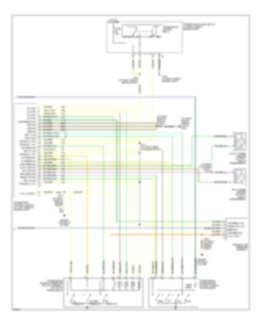
A/T Wiring Diagram, without Autostick (1 of 2) for Dodge Charger SE 2007
List of elements for A/T Wiring Diagram, without Autostick (1 of 2) for Dodge Charger SE 2007:
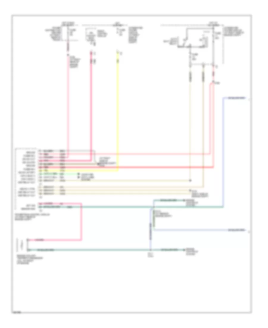
A/T Wiring Diagram, without Autostick (2 of 2) for Dodge Charger SE 2007
List of elements for A/T Wiring Diagram, without Autostick (2 of 2) for Dodge Charger SE 2007: