TRANSMISSION
4WD Wiring Diagram for Ford Cab & Chassis F350 Super Duty 2001

List of elements for 4WD Wiring Diagram for Ford Cab & Chassis F350 Super Duty 2001:
- (excursion)
- (pickup)
- 4 wheel drive mode switch
- 4x2 sol
- 4x4 high ind
- 4x4 high range indicator
- 4x4 low ind
- 4x4 low range indicator
- 4x4 mode sw
- 4x4 sol
- 87a
- Anti-lock brake system module (left front of engine compt)
- Battery junction box (left side of engine compt)
- Bpp sw input
- Brake pedal position switch (behind left side of dash)
- C1040
- C240a
- C240c
- C242b
- C250a
- C2530c
- C285a
- C285b
- Central junction box (lower left side of dash)
- Contact plate a
- Contact plate b
- Contact plate c
- Contact plate p
- Digital transmission range (dtr) sensor (left side of transmission)
- Encoder ground
- Fuse 10a
- Fuse 17 (pickup) 104 (excursion) 30a
- Fuse 20a
- Fuse 28 (pickup) 6 (excursion) 10a (pickup) 15a (excursion)
- G100 (left rear of engine compt)
- G300 (left kick panel)
- Generic electronic module (gem) (behind left side of dash)
- H2l rly ctrl
- High to low
- Hot at all times
- Hot in run
- Hot in run or start
- Idle validation switch, overhead trip computer module, overdrive cancel switch, passive anti-theft system transceiver module
- Ignition
- Illumination
- Instrument cluster
- Interior lights (instrument illumination)
- L2h rly ctrl
- Low to high
- Neutral sw in
- Not used
- Powertrain control module, instrument cluster
- Red
- S111 (pickup only) (engine harn, left side of eng compt)
- S124
- S201
- S205
- S206
- S213
- S221
- S250
- S251
- S255 (main harn, near transer case assembly)
- S271
- Shift lock actuator, drl relay
- Shift motor
- Sw a input
- Sw b input
- Sw c input
- Sw d input
- Tod rly ctrl
- Transfer case
- Transfer case assembly (below vehicle, behind transmission)
- Transfer case shift relay module (left side of eng compt)
- Vacuum hublock solenoid (right side of engine compt)
- Vacuum pump, speed control module, digital transmission range sensor
- Vcc
5.4L
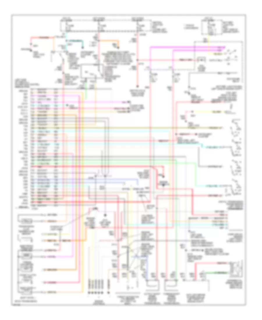
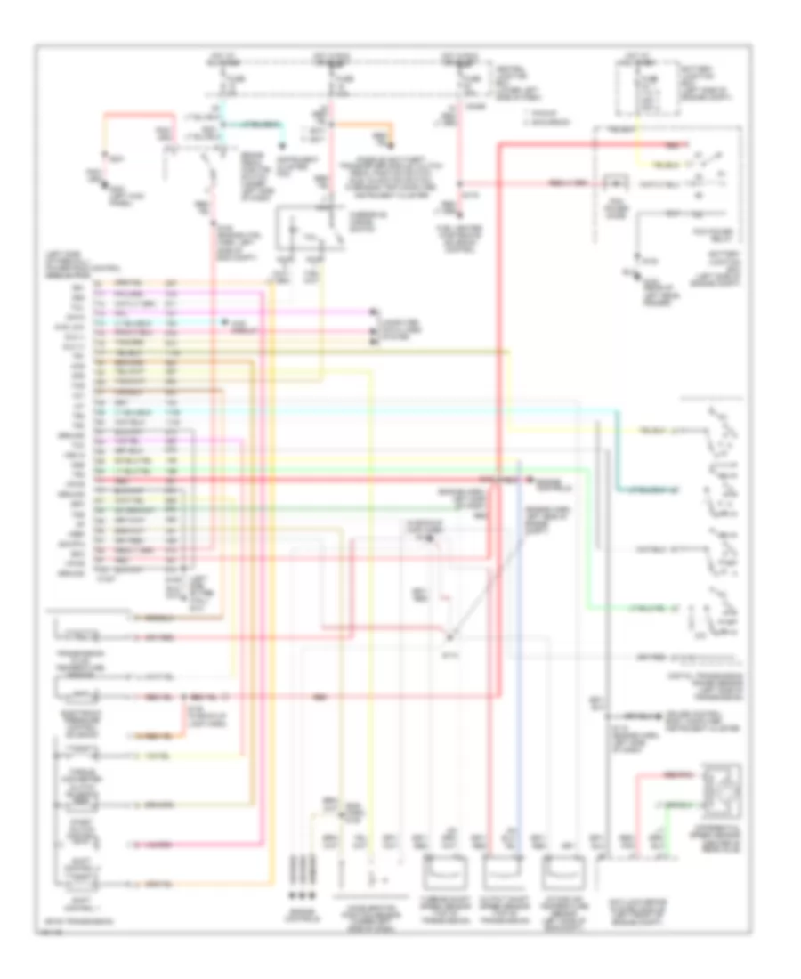
5.4L, A/T Wiring Diagram for Ford Cab & Chassis F350 Super Duty 2001
List of elements for 5.4L, A/T Wiring Diagram for Ford Cab & Chassis F350 Super Duty 2001:
- (bi-fuel only)
- (engine harn, left side of dash) s122
- (engine harn, left side of eng compt)
- (engine harn, near aftermarket circuits breakout)
- (engine harn, near breakout to fuel injector 6 or 7)
- (in back-up lamp harn)
- (left side of firewall) powertrain control module (pcm)
- (top left front of eng) engine coolant temperature sender
- (vcl/sens harn, right rear of eng compt)
- 4r100 transmission
- 4wd circuit
- 4wd low
- Anti-lock brake system module (left front of engine compt)
- Battery junction box (left side of engine compt)
- Bi-fuel
- Boo
- Brake pedal position switch (under left side of dash)
- C1027
- C242b
- Calif only w/o bi- fuel
- Ccs
- Central junction box (lower left side of dash)
- Coast clutch control
- Computer data lines system
- Cruise control, body computer, instrument cluster
- Data
- Differential speed sensor (center of rear axle)
- Digital transmission range sensor (left side of transmission)
- Dlc (+)
- Dlc (-)
- Ect
- Electronic pressure cntrl sol
- Engine controls
- Epc
- Fuse 10a
- Fuse 20a
- Fuse 30a
- Fuse 30a 20a
- Fuse 5a
- G100 (rear of left front fender)
- G101 (left side of fire- wall)
- G101 (left side of firewall)
- G300 (left kick panel)
- Gasoline
- Ground
- Hot at all times
- Hot in run or start
- Iat
- Ignition coils, radio noise capacitor
- Instrument cluster
- Instrument cluster, pcm
- Maf
- Mass airlow sensor (left front of eng compt)
- Nca
- Oss
- Output shaft speed sensor (top of transmission)
- Overdrive cancel switch (end of transmission selector lever)
- Passive anti-theft transciever module, clutch pedal position switch, idle validation switch, overhead trip computer, instrument cluster
- Pcm power diode
- Pcm power relay
- Pickup excursion
- R p
- Red
- Red/ pnk
- Red/pnk
- S102
- S104 (eng harn, left side of eng compt)
- S106
- S114
- S115 (engine harn, left side of dash)
- S123 (eng harn, left side of dash)
- S128
- S132
- S133
- S138
- S139
- S179
- S201
- S213
- S271
- S4021
- Shift cntrl 1
- Shift cntrl 2
- Side of eng compt)
- Sig rtn
- Ss1
- Ss2
- Tcc
- Tcil
- Tcs
- Tft
- Throttle position (tp) sensor (on throttle body)
- Torque converter clutch sol
- Tr1
- Tr2
- Tr3
- Tr4
- Transmission fluid temperature sensor
- Tss
- Turbine shaft speed sensor (top of transmission)
- Vpwr
- Vref
- Vss in
6.8L
6.8L, A/T Wiring Diagram for Ford Cab & Chassis F350 Super Duty 2001
List of elements for 6.8L, A/T Wiring Diagram for Ford Cab & Chassis F350 Super Duty 2001:
- (bi-fuel only)
- (engine harn, left side of dash) s122
- (engine harn, left side of eng compt)
- (engine harn, near aftermarket circuits breakout)
- (engine harn, near breakout to fuel injector 6 or 7)
- (in back-up lamp harn)
- (left side of firewall) powertrain control module (pcm)
- (top left front of eng) engine coolant temperature sender
- (vcl/sens harn, right rear of eng compt)
- 4r100 transmission
- 4wd circuit
- 4wd low
- Anti-lock brake system module (left front of engine compt)
- Battery junction box (left side of engine compt)
- Bi-fuel
- Boo
- Brake pedal position switch (under left side of dash)
- C1027
- C242b
- Calif only w/o bi- fuel
- Ccs
- Central junction box (lower left side of dash)
- Coast clutch control
- Computer data lines system
- Cruise control, body computer, instrument cluster
- Data
- Differential speed sensor (center of rear axle)
- Digital transmission range sensor (left side of transmission)
- Dlc (+)
- Dlc (-)
- Ect
- Electronic pressure cntrl sol
- Engine controls
- Epc
- Fuse 10a
- Fuse 20a
- Fuse 30a
- Fuse 30a 20a
- Fuse 5a
- G100 (rear of left front fender)
- G101 (left side of fire- wall)
- G101 (left side of firewall)
- G300 (left kick panel)
- Gasoline
- Ground
- Hot at all times
- Hot in run or start
- Iat
- Ignition coils, radio noise capacitor
- Instrument cluster
- Instrument cluster, pcm
- Maf
- Mass airlow sensor (left front of eng compt)
- Nca
- Oss
- Output shaft speed sensor (top of transmission)
- Overdrive cancel switch (end of transmission selector lever)
- Passive anti-theft transciever module, clutch pedal position switch, idle validation switch, overhead trip computer, instrument cluster
- Pcm power diode
- Pcm power relay
- Pickup excursion
- R p
- Red
- Red/ pnk
- Red/pnk
- S102
- S104 (eng harn, left side of eng compt)
- S106
- S114
- S115 (engine harn, left side of dash)
- S123 (eng harn, left side of dash)
- S128
- S132
- S133
- S138
- S139
- S179
- S201
- S213
- S271
- S4021
- Shift cntrl 1
- Shift cntrl 2
- Side of eng compt)
- Sig rtn
- Ss1
- Ss2
- Tcc
- Tcil
- Tcs
- Tft
- Throttle position (tp) sensor (on throttle body)
- Torque converter clutch sol
- Tr1
- Tr2
- Tr3
- Tr4
- Transmission fluid temperature sensor
- Tss
- Turbine shaft speed sensor (top of transmission)
- Vpwr
- Vref
- Vss in
6.8L BI-FUEL
6.8L Bi-Fuel, A/T Wiring Diagram for Ford Cab & Chassis F350 Super Duty 2001
List of elements for 6.8L Bi-Fuel, A/T Wiring Diagram for Ford Cab & Chassis F350 Super Duty 2001:
- (bi-fuel only)
- (engine harn, left side of dash) s122
- (engine harn, left side of eng compt)
- (engine harn, near aftermarket circuits breakout)
- (engine harn, near breakout to fuel injector 6 or 7)
- (in back-up lamp harn)
- (left side of firewall) powertrain control module (pcm)
- (top left front of eng) engine coolant temperature sender
- (vcl/sens harn, right rear of eng compt)
- 4r100 transmission
- 4wd circuit
- 4wd low
- Anti-lock brake system module (left front of engine compt)
- Battery junction box (left side of engine compt)
- Bi-fuel
- Boo
- Brake pedal position switch (under left side of dash)
- C1027
- C242b
- Calif only w/o bi- fuel
- Ccs
- Central junction box (lower left side of dash)
- Coast clutch control
- Computer data lines system
- Cruise control, body computer, instrument cluster
- Data
- Differential speed sensor (center of rear axle)
- Digital transmission range sensor (left side of transmission)
- Dlc (+)
- Dlc (-)
- Ect
- Electronic pressure cntrl sol
- Engine controls
- Epc
- Fuse 10a
- Fuse 20a
- Fuse 30a
- Fuse 30a 20a
- Fuse 5a
- G100 (rear of left front fender)
- G101 (left side of fire- wall)
- G101 (left side of firewall)
- G300 (left kick panel)
- Gasoline
- Ground
- Hot at all times
- Hot in run or start
- Iat
- Ignition coils, radio noise capacitor
- Instrument cluster
- Instrument cluster, pcm
- Maf
- Mass airlow sensor (left front of eng compt)
- Nca
- Oss
- Output shaft speed sensor (top of transmission)
- Overdrive cancel switch (end of transmission selector lever)
- Passive anti-theft transciever module, clutch pedal position switch, idle validation switch, overhead trip computer, instrument cluster
- Pcm power diode
- Pcm power relay
- Pickup excursion
- R p
- Red
- Red/ pnk
- Red/pnk
- S102
- S104 (eng harn, left side of eng compt)
- S106
- S114
- S115 (engine harn, left side of dash)
- S123 (eng harn, left side of dash)
- S128
- S132
- S133
- S138
- S139
- S179
- S201
- S213
- S271
- S4021
- Shift cntrl 1
- Shift cntrl 2
- Side of eng compt)
- Sig rtn
- Ss1
- Ss2
- Tcc
- Tcil
- Tcs
- Tft
- Throttle position (tp) sensor (on throttle body)
- Torque converter clutch sol
- Tr1
- Tr2
- Tr3
- Tr4
- Transmission fluid temperature sensor
- Tss
- Turbine shaft speed sensor (top of transmission)
- Vpwr
- Vref
- Vss in
7.3L DIESEL
7.3L Diesel, A/T Wiring Diagram for Ford Cab & Chassis F350 Super Duty 2001
List of elements for 7.3L Diesel, A/T Wiring Diagram for Ford Cab & Chassis F350 Super Duty 2001:
- (eng harn) s128
- (engine harn, left side of dash)
- (engine harn, left side of engine compt)
- (in backup lamp harn) s139
- (left side of fire- wall) g101
- (left side of firewall) powertrain control module (pcm)
- 4r100 transmission
- 4wd circuit
- 4wd low
- Accelerator position sensor (under left side of dash)
- Anti-lock brake system module (left front of engine compt)
- Aps
- Battery junction box (left side of engine compt)
- Boo
- Brake pedal position switch (under left side of dash)
- C1027
- C242b
- Ccs
- Central junction box (lower left side of dash)
- Coast clutch control
- Computer data lines system
- Cruise control, body computer, instrument cluster
- Data
- Differential speed sensor (center of rear axle)
- Digital transmission range sensor (left side of transmission)
- Dlc (+)
- Dlc (-)
- Electronic pressure control solenoid
- Engine controls
- Epc
- Excursion
- Fuel heater, wastegate solenoid control
- Fuse 10a
- Fuse 30a
- Fuse 30a 20a
- Fuse 5a
- G100 (rear of left rear fender)
- G300 (left kick panel)
- Ground
- Hot at all times
- Hot in run or start
- Iat
- Instrument cluster, pcm
- Intake air temperature sensor (left side of eng compt)
- Nca
- Oss
- Output shaft speed sensor (top of transmission)
- Overdrive cancel switch
- Passive anti-theft transceiver module, clutch pedal position switch, idle validation switch, overhead trip computer, instrument cluster
- Pcm power diode
- Pcm power relay
- Pickup
- R p
- Red
- Red/ pnk
- Red/pnk
- S102
- S106
- S108 (engine ctrl harn, left side of eng compt)
- S114
- S115 (engine harn, left side of dash)
- S123
- S138 (in back-up lamp harn)
- S179
- S201
- S213
- S221
- S271
- Shift control 1
- Shift control 2
- Sig rtn
- Ss1
- Ss2
- Tcc
- Tcil
- Tcs
- Tft
- Torque converter clutch solenoid
- Tr1
- Tr2
- Tr3
- Tr4
- Transmission fluid temperature sensor
- Tss
- Turbine shaft speed sensor (top of transmission)
- Vpwr
- Vref
- Vss in