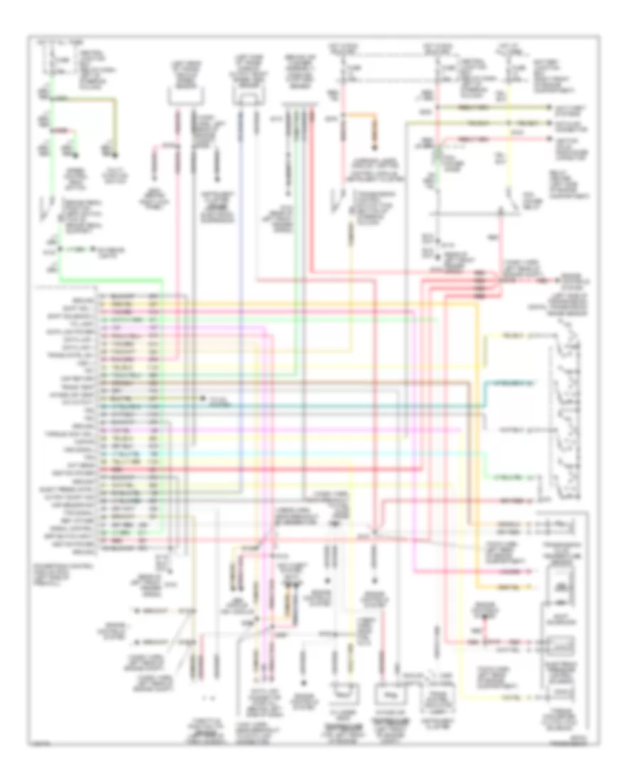
TRANSMISSION
Transmission Wiring Diagram for Ford Crown Victoria Police Interceptor 1998
List of elements for Transmission Wiring Diagram for Ford Crown Victoria Police Interceptor 1998:
- (12a581 harn, left rear of engine compt)
- (12a581 harn, left rear of engine compt) s129
- (12a581 harn, near breakout to fuel pump prime)
- (12b636 harn, near breakout to generator)
- (12b637 harn, near fuel inj 8)
- (14401 harn, near breakout to data link connector)
- (7c078 harn, left rear of engine compartment)
- (behind air cleaner assembly) mass air- flow (maf) sensor
- (left rear of trans) vehicle speed sensor
- (left side of trans- mission) output shaft speed (oss) sensor
- (left side of transmission) digital transmission range sensor
- (rear of left front fender apron)
- (rear of left front fender g104 apron)
- 4r70w transmission
- A/c cutout
- Abs module,
- Analog
- Anti-theft system,
- Anti-theft systems
- Battery junction box (right front of engine compartment)
- Bpp switch input
- Brake pedal position (bpp) switch (top of brake pedal support)
- C250
- C255
- Central junction box (below dash, left of steering column)
- Cht sens
- Control module, instrument cluster
- Cylinder head
- Data link +
- Data link -
- Data link connector (partial) (behind left side of dash)
- Data link power
- Datalink connector
- Digital
- Eatc module
- Elect press cntrl
- Electronic pressure control solenoid
- Engine controls system
- Exterior lights
- Fuse 15a
- Fuse 25a
- Fuse 30a
- G104
- G104 (rear of left front fender apron)
- G203 (behind
- Ground
- Hot at all times
- Hot in run or start
- Ignition coils, radio noise capacitor
- Ignition power
- Instrument cluster
- Instrument cluster, cruise control, electronic suspension
- Intake air
- Intake air temp
- Kapwr
- Maf return
- Maf sensor sig
- Multi- function switch
- Ngv module
- Output shaft sig
- Pcm power diode
- Pcm power relay
- Powertrain control module (pcm) (left side of firewall)
- R p
- Red
- Red red
- Ref votage
- Relay center (left side of engine compartment)
- Right kick panel)
- S100
- S105
- S115
- S119
- S123
- S125
- S126
- S132
- S134
- S135
- S147
- S148
- S223
- S263
- S265
- S276
- S296
- S297
- Shift sol 1
- Shift solenoid 2
- Shift solenoids
- Signal control
- Speed control deac switch
- Ss1
- Ss2
- Tci lamp
- Temperature (cht) sensor (top left front of engine)
- Temperature (iat) sensor (left front of engine) compt)
- Throttle position (tp) sensor (left side of throtle body)
- To a/c system
- Torque conv sol
- Torque converter clutch (tcc) solenoid
- Tps signal
- Tr1
- Tr2
- Tr3
- Tr4
- Trans cntrl sw
- Trans control indicator lamp
- Trans temp
- Transmission control switch (tcs) (bottom of steering column)
- Transmission fluid temperature sensor
- Vss (-)
- Vss signal
- Warning lamps module, lighting
 English