TRANSMISSION
4.6L
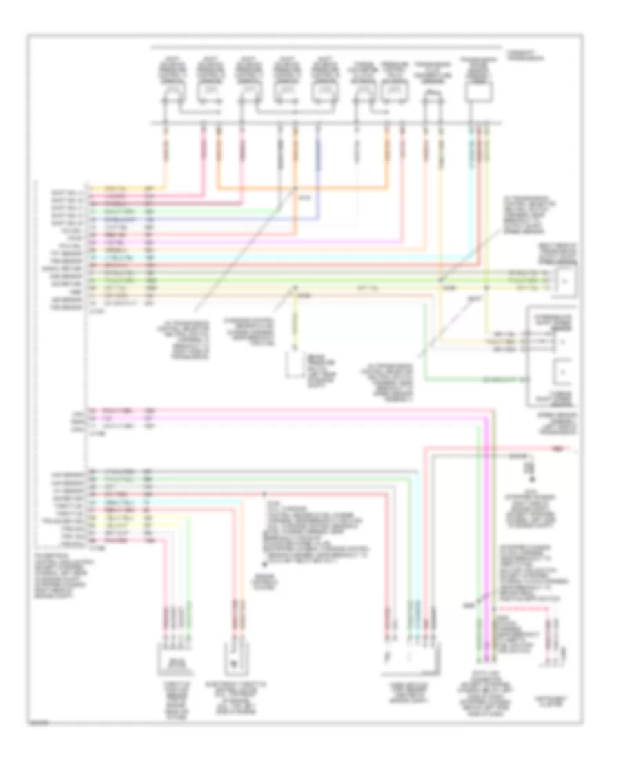
4.6L, Transmission Wiring Diagram (1 of 2) for Ford Econoline E250 2008

List of elements for 4.6L, Transmission Wiring Diagram (1 of 2) for Ford Econoline E250 2008:
- (in transmission control selector neutral switch harness, near breakout to output shaft speed (oss) sensor) s198
- (left side of transmission) digital transmission range (dtr) sensor
- (left side of transmission) output shaft speed (oss) sensor
- 4.6l
- 4r75e transmission
- 5.4l
- C175b
- C175e
- C175t
- C220a
- Can+
- Can-
- Data link connector (below left side of dash)
- Dtr tr1
- Dtr tr2
- Dtr tr3a
- Dtr tr4
- Electronic pressure control solenoid
- Electronic throttle control (etc) motor (top front of engine)
- Electronic throttle control module (top front of engine)
- Engine controls system
- Epc sol
- Exterior lights system
- Feps
- G104 (left side of of engine compt)
- Iat sensor
- In main harness, near breakout to brake pedal position (bpp) switch)
- Instrument cluster
- Maf return
- Maf sensor
- Mass air flow (maf) sensor (center of engine compt)
- Oss sig
- Powertrain control module (pcm) (left rear of engine compt)
- Red
- S136 (4.6l: in engine control sensor & fuel charge harness, near breakout for c192)
- S172
- S228 (in main harness, near breakout to inertia fuel shutoff (ifs) switch)
- S269
- Shift sol a
- Shift sol b
- Shift solenoids
- Sig return
- Solid state
- Starting/ charging system
- Tan/red
- Tcc sol
- Tft sensor sig
- Throttle position sensor (tps) (top of engine, near air intake)
- Throttle+
- Throttle-
- Torque converter clutch solenoid
- Tps pow
- Tps sig return
- Tps1 sig
- Tps2 sig
- Transmission fluid temperature sensor
- Tss sensor
- Turbine shaft speed (tss) sensor (left side of transmission)
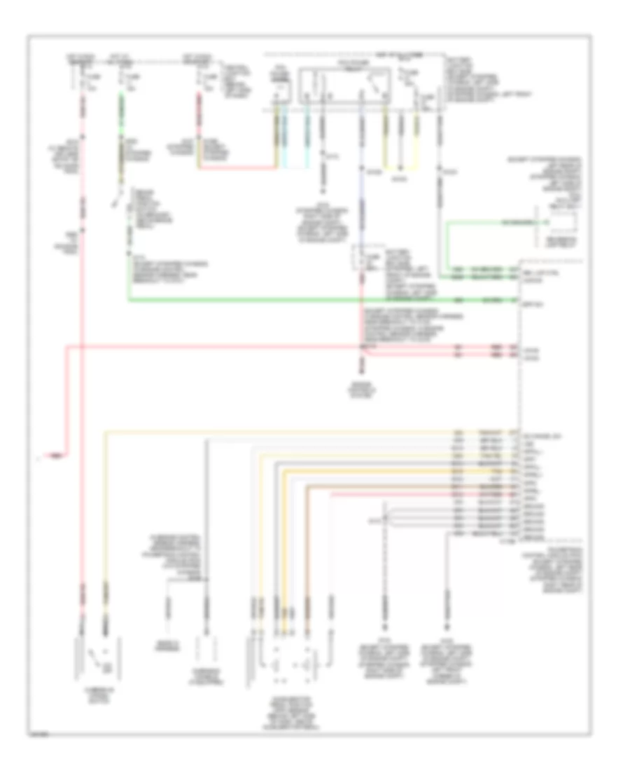
4.6L, Transmission Wiring Diagram (2 of 2) for Ford Econoline E250 2008
List of elements for 4.6L, Transmission Wiring Diagram (2 of 2) for Ford Econoline E250 2008:
- (ends in harness)
- (in engine control sensor harness, near breakout to c140) s142
- (in engine control sensor harness, near breakout to powertrain control module (pcm)) s135
- (in transmission control selector neutral switch harness, near breakout to c192) s100
- Accelerator pedal position (app) sensor (behind left side of dash, above accelerator pedal)
- App1
- App2
- App3
- Appa_+
- Appa_-
- Appb_+
- Appb_-
- Battery junction box (bjb) (left side of engine compt)
- Bpp sw
- Brake pedal position switch (on bracket, above brake pedal)
- C175b
- Central junction box (behind left side of dash)
- Engine controls system
- Fuse 10a
- Fuse 15a
- Fuse 20a
- Fuse 30a
- G100 (left side of engine compt)
- G104 (left side of engine compt)
- Ground
- Hot at all times
- Hot in run or start
- Kapwr
- Nca
- O/d off
- Od cancel sw
- Overdrive cancel switch
- Overhead console (if equipped)
- Pcm power diode
- Pcm power relay
- Powertrain control module (pcm) (left rear of engine compt)
- Red
- S1021
- S1033
- S1035
- S1065
- S172
- S174 (in engine control sensor harness, near breakout to g101)
- S216 (w/ remote keyless entry or advance trac)
- S260 (w/ advance trac)
- S282
- Tan
- Vpwr
- Vss
5.4L
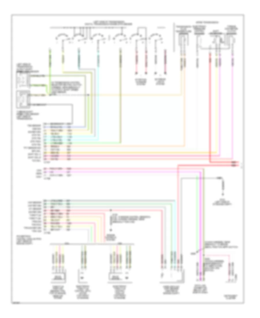
5.4L, Transmission Wiring Diagram, with Torqshift (1 of 2) for Ford Econoline E250 2008
List of elements for 5.4L, Transmission Wiring Diagram, with Torqshift (1 of 2) for Ford Econoline E250 2008:
- (in engine control sensor & fuel charge harness, near breakout for c192)
- (in transmission control selector neutral switch harness, in breakout to right side of transmission)
- (in transmission control selector neutral switch harness, near breakout to output shaft speed sensor)
- (in transmission control selector neutral switch harness, near breakout to speed sensor assembly)
- (right rear of transmission) output shaft speed sensor
- (stripped chassis: in main harness, near breakout to inertia fuel shutoff (ifs) switch) (except stripped chassis: in main harness, near breakout to brake pedal position (bpp) switch)
- Auxiliary relay box no 1)
- Brake pressure switch (left rear of engine compt)
- C175b
- C175e
- C175t
- C220a
- Can+
- Can-
- Data link connector (except stripped chassis: below left side of dash) (stripped chassis: behind left side side of dash)
- Electronic throttle control motor (5.4l: top front of engine) (6.8l: top left side of engine)
- Engine controls system
- Feps
- G104 (stripped chassis: right side of engine compt) (except stripped chassis: left side of engine compt)
- Iat sensor
- Instrument cluster
- Intermediate shaft speed sensor
- Iss sensor
- Maf sensor
- Mass air flow (maf) sensor (center of engine compt)
- Oss sensor
- Pc-a sol
- Powertrain control module (pcm) (except stripped chassis: left rear of engine compt) (stripped chassis: right rear of engine compt)
- Pressure control (pc-a) solenoid
- Red
- S1037
- S123
- S139
- S172
- S198
- S269
- Shift sol a
- Shift sol b
- Shift sol c
- Shift sol d
- Shift sol e
- Shift solenoid pressure control a (sspc-a)
- Shift solenoid pressure control b (sspc-b)
- Shift solenoid pressure control c (sspc-c)
- Shift solenoid pressure control d (sspc-d)
- Shift solenoid pressure control e (sspc-e)
- Sig return
- Signal return
- Solid state
- Speed sensor assembly (left side of transmission)
- Tcc sol
- Tft sensor
- Throttle position sensor (top of engine, near air intake)
- Throttle+
- Throttle-
- Torqshift transmission
- Torque converter clutch solenoid
- Tps pow
- Tps sig return
- Tps1 sig
- Tps2 sig
- Transmission fluid temperature sensor
- Transmission range sensor assembly (tr-p)
- Trs sensor
- Tss sensor
- Turbine shaft speed sensor
- Vpwr
- Vref
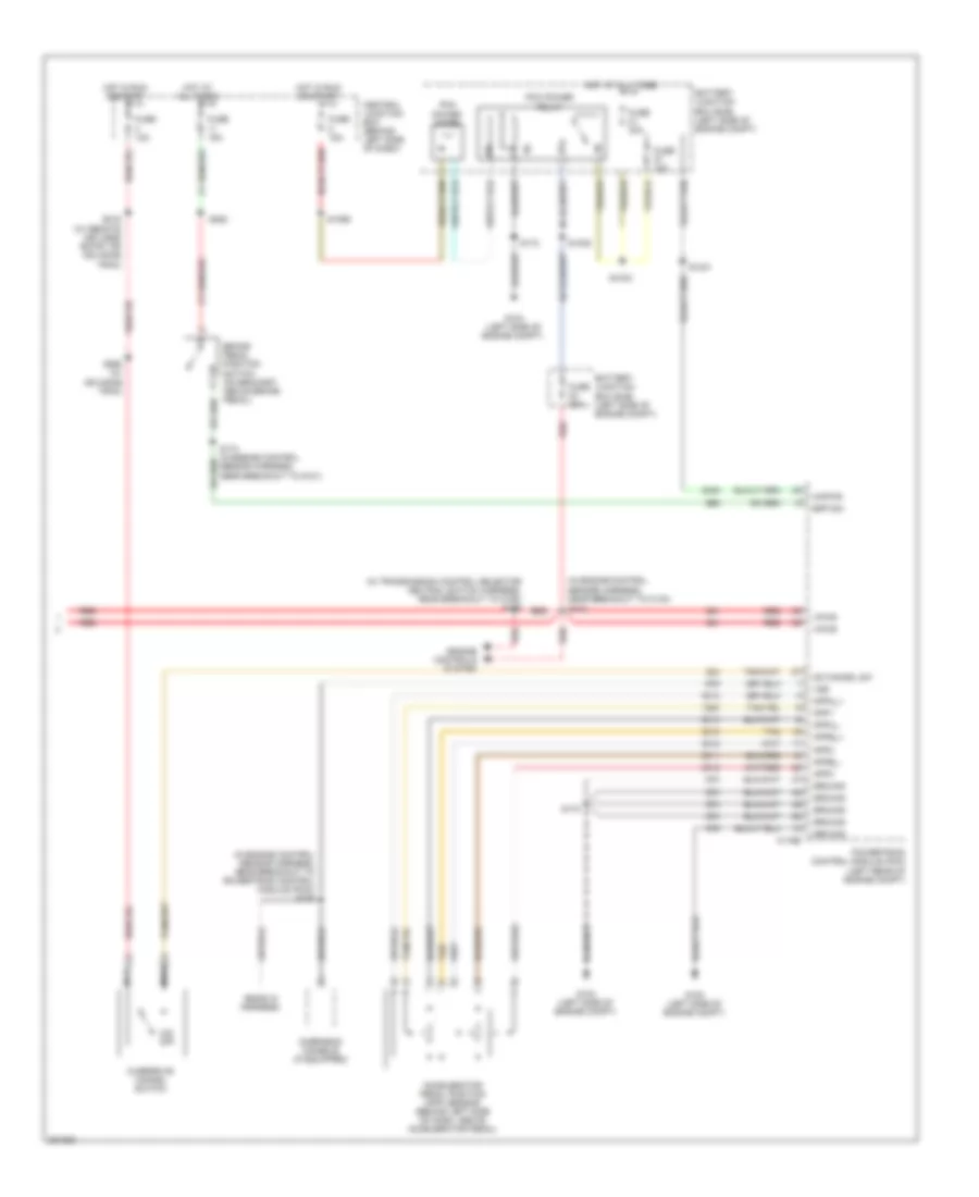
5.4L, Transmission Wiring Diagram, with Torqshift (2 of 2) for Ford Econoline E250 2008
List of elements for 5.4L, Transmission Wiring Diagram, with Torqshift (2 of 2) for Ford Econoline E250 2008:
- (ends in harness)
- (except stripped chassis: in engine control sensor harness, near breakout to c140) (stripped chassis: in engine control sensor harness, near breakout to c219) s142
- (except stripped chassis: left rear of engine compt) (stripped chassis: left side of engine compt) (6.8l) auxiliary relay box 1
- (except stripped chassis: left side of engine compt) (stripped chassis: left front corner of engine compt)
- (except stripped chassis: left side of engine compt) (stripped chassis: right side of engine compt)
- (in engine control sensor harness, near breakout to powertrain control module (pcm) (w/o stripped chassis) s135
- Accelerator pedal position (app) sensor (behind left side of dash, above accelerator pedal)
- App1
- App2
- App3
- Appa_+
- Appa_-
- Appb_+
- Appb_-
- Battery junction box (bjb) (except stripped chassis: left side of engine compt) (stripped chassis: left front of engine compt)
- Battery junction box (bjb) (stripped: left front of engine compt) (except stripped chassis: left side of engine compt)
- Bpp sw
- Brake pedal position switch (on bracket, above brake pedal)
- C175b
- Central junction box (behind left side of dash)
- Engine controls system
- Fuse 10a
- Fuse 15a
- Fuse 20a
- Fuse 30a
- G100
- G104
- G104 (stripped chassis: right side of engine compt) (except stripped chassis: left side of engine compt)
- Ground
- Hot at all times
- Hot in run or start
- Kapwr
- Nca
- O/d off
- Od cancel sw
- Overdrive cancel switch
- Overhead console (if equipped)
- Pcm power diode
- Pcm power relay
- Powertrain control module (pcm) (except stripped chassis: left rear of engine compt) (stripped chassis: right rear of engine compt)
- Red
- Rev lmp ctrl
- Reversing lamp relay
- S1021
- S1033
- S1035
- S1065 (except stripped chassis)
- S127 (stripped chassis)
- S172
- S174 (except stripped chassis) (in engine control sensor harness, near breakout to g101)
- S216 (w/ remote keyless entry or advance trac)
- S260 (w/ advance trac)
- S282 (w/ stripped chassis)
- Tan
- Vpwr
- Vss
5.4L, Transmission Wiring Diagram, without Torqshift (1 of 2) for Ford Econoline E250 2008
List of elements for 5.4L, Transmission Wiring Diagram, without Torqshift (1 of 2) for Ford Econoline E250 2008:
- (in transmission control selector neutral switch harness, near breakout to output shaft speed (oss) sensor) s198
- (left side of transmission) digital transmission range (dtr) sensor
- (left side of transmission) output shaft speed (oss) sensor
- 4.6l
- 4r75e transmission
- 5.4l
- C175b
- C175e
- C175t
- C220a
- Can+
- Can-
- Data link connector (below left side of dash)
- Dtr tr1
- Dtr tr2
- Dtr tr3a
- Dtr tr4
- Electronic pressure control solenoid
- Electronic throttle control (etc) motor (top front of engine)
- Electronic throttle control module (top front of engine)
- Engine controls system
- Epc sol
- Exterior lights system
- Feps
- G104 (left side of of engine compt)
- Iat sensor
- In main harness, near breakout to brake pedal position (bpp) switch)
- Instrument cluster
- Maf return
- Maf sensor
- Mass air flow (maf) sensor (center of engine compt)
- Oss sig
- Powertrain control module (pcm) (left rear of engine compt)
- Red
- S136 (4.6l: in engine control sensor & fuel charge harness, near breakout for c192)
- S172
- S228 (in main harness, near breakout to inertia fuel shutoff (ifs) switch)
- S269
- Shift sol a
- Shift sol b
- Shift solenoids
- Sig return
- Solid state
- Starting/ charging system
- Tan/red
- Tcc sol
- Tft sensor sig
- Throttle position sensor (tps) (top of engine, near air intake)
- Throttle+
- Throttle-
- Torque converter clutch solenoid
- Tps pow
- Tps sig return
- Tps1 sig
- Tps2 sig
- Transmission fluid temperature sensor
- Tss sensor
- Turbine shaft speed (tss) sensor (left side of transmission)
5.4L, Transmission Wiring Diagram, without Torqshift (2 of 2) for Ford Econoline E250 2008
List of elements for 5.4L, Transmission Wiring Diagram, without Torqshift (2 of 2) for Ford Econoline E250 2008:
- (ends in harness)
- (in engine control sensor harness, near breakout to c140) s142
- (in engine control sensor harness, near breakout to powertrain control module (pcm)) s135
- (in transmission control selector neutral switch harness, near breakout to c192) s100
- Accelerator pedal position (app) sensor (behind left side of dash, above accelerator pedal)
- App1
- App2
- App3
- Appa_+
- Appa_-
- Appb_+
- Appb_-
- Battery junction box (bjb) (left side of engine compt)
- Bpp sw
- Brake pedal position switch (on bracket, above brake pedal)
- C175b
- Central junction box (behind left side of dash)
- Engine controls system
- Fuse 10a
- Fuse 15a
- Fuse 20a
- Fuse 30a
- G100 (left side of engine compt)
- G104 (left side of engine compt)
- Ground
- Hot at all times
- Hot in run or start
- Kapwr
- Nca
- O/d off
- Od cancel sw
- Overdrive cancel switch
- Overhead console (if equipped)
- Pcm power diode
- Pcm power relay
- Powertrain control module (pcm) (left rear of engine compt)
- Red
- S1021
- S1033
- S1035
- S1065
- S172
- S174 (in engine control sensor harness, near breakout to g101)
- S216 (w/ remote keyless entry or advance trac)
- S260 (w/ advance trac)
- S282
- Tan
- Vpwr
- Vss