TRANSMISSION
4.6L
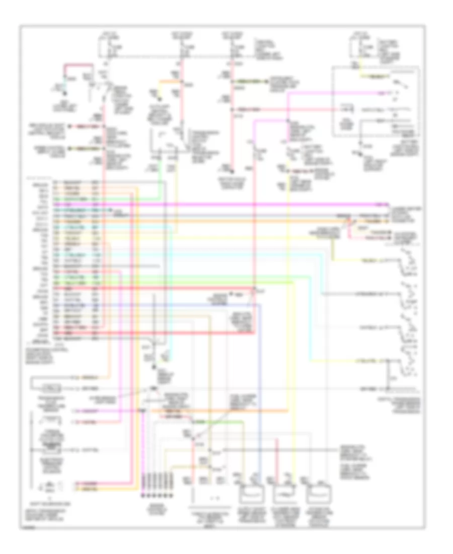
4.6L, A/T Wiring Diagram, 4R100 for Ford Expedition 2002

List of elements for 4.6L, A/T Wiring Diagram, 4R100 for Ford Expedition 2002:
- (5.4l)
- (dash harn, near breakout to cluster)
- (eng ctrl harn, near breakout to wiper motor)
- (engine ctrl harn, near breakout to starter relay)
- (engine ctrl harn, right rear of eng compt)
- (fuel charge harn, near breakout to ho2s 21)
- (fuel charge harn, near breakout to knock sensor)
- (in reversing lamp harn)
- (rear of engine compt) g101
- (right side of engine compt) powertrain control module
- (under center of dash) data link connector
- 4r100 transmission
- 4wd circuit
- 4x4 low
- A/c system, instrument cluster
- Autolamp, central security & belt minder modules
- Battery junction box (left side of engine compt)
- Bpp
- Brake pedal position switch (under left side of dash)
- Breakout to cluster)
- C174
- C243
- Ccs
- Central junction box (under left side of dash)
- Cht
- Coast clutch control
- Cylinder head temperature (cht) sensor (top front of engine)
- Data
- Digital transmission range sensor (left side of transmission)
- Dlc (+)
- Dlc (-)
- Electronic pressure control solenoid
- Engine controls system
- Epc
- Fuse 15a
- Fuse 30a
- Fuse 5a
- G104 (left front radiator support)
- G201 (lower left kick panel)
- Gem module, shift lock actuator, central security module
- Ground
- Hot at all times
- Hot in run or start
- Iat
- Ignition coils, radio noise capacitor
- Instrument cluster, pats transceiver module
- Intake air temperature sensor (on intake manifold)
- Nca
- Oss
- Output shaft speed sensor (left side of transmission)
- Pcm power diode
- Pcm power relay
- R p
- Red
- S101
- S106
- S116
- S127
- S130 (engine ctrl harn, left rear of eng compt)
- S134 (left rear corner of eng compt)
- S135
- S136
- S137
- S138
- S140
- S141
- S160 (engine ctrl harn, left rear of eng compt)
- S2002
- S2007
- S2008
- S208
- S225
- Shift solenoid a
- Shift solenoid b
- Sig rtn
- Speed control servo, 4wabs module
- Ss a
- Ss b
- Tcc
- Tcil
- Tcs
- Tft
- Throttle position (tp) sensor (on throttle body)
- Torque converter clutch solenoid
- Tr1
- Tr2
- Tr3
- Tr4
- Transmission control switch (tcs) (end of transmission selector lever)
- Transmission fluid temperature sensor
- Tss
- Turbine shaft speed sensor (5.4l) (left side of transmission)
- Vpwr
- Vref
4.6L, A/T Wiring Diagram, 4R70W for Ford Expedition 2002
List of elements for 4.6L, A/T Wiring Diagram, 4R70W for Ford Expedition 2002:
- (dash harn, near breakout to cluster)
- (eng ctrl harn, near breakout to wiper motor)
- (engine ctrl harn, near breakout to starter relay)
- (engine ctrl harn, right rear of engine compt)
- (fuel charge harn, near breakout to ho2s 21)
- (fuel charge harn, near breakout to knock sensor)
- (in reversing lamp harn)
- (under center of dash) data link connector
- 4r70w transmission (mounted under center of vehicle)
- 4wd circuit
- 4x4 low
- A/c system, instrument cluster
- Autolamp, central security & belt minder modules
- Battery junction box (left side of engine compt)
- Bpp
- Brake pedal position switch (under left side of dash)
- Breakout to cluster)
- C174
- C243
- Central junction box (under left side of dash)
- Cht
- Cylinder head temperature (cht) sensor (top front of engine)
- Data
- Digital transmission range sensor (left side of transmission)
- Dlc (+)
- Dlc (-)
- Electronic pressure control solenoid
- Engine controls system
- Epc
- Fuse 15a
- Fuse 30a
- Fuse 5a
- G101 (rear of engine compt)
- G104 (left front radiator support)
- G201 (lower left kick panel)
- Gem module, shift lock actuator, central security module
- Ground
- Hot at all times
- Hot in run or start
- Iat
- Ignition coils, radio noise capacitor
- Instrument cluster, pats transceiver module
- Intake air temperature sensor (on intake manifold)
- Nca
- Oss
- Output shaft speed sensor (left side of transmission)
- Pcm power diode
- Pcm power relay
- Powertrain control module (pcm) (right side of engine compt)
- R p
- Red
- S101
- S106
- S116
- S127
- S130 (engine ctrl harn, left rear of eng compt)
- S134 (left rear corner of eng compt)
- S135
- S136
- S137
- S138
- S140
- S141
- S160 (engine ctrl harn, left rear of eng compt)
- S2002
- S2007
- S2008
- S208
- S225
- Shift solenoids (ss)
- Sig rtn
- Speed control servo, 4wabs module
- Ss a
- Ss b
- Tcc
- Tcil
- Tcs
- Tft
- Throttle position (tp) sensor (on throttle body)
- Torque converter clutch (tcc) solenoid
- Tr1
- Tr2
- Tr3
- Tr4
- Transmission control switch (tcs) (end of transmission selector lever)
- Transmission fluid temperature sensor
- Vpwr
- Vref
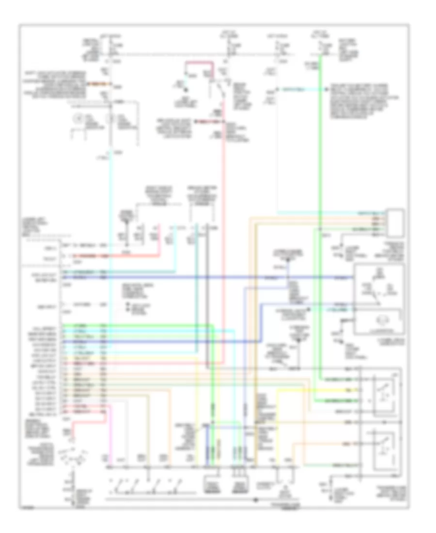
4WD Wiring Diagram for Ford Expedition 2002
List of elements for 4WD Wiring Diagram for Ford Expedition 2002:
- (4h) ohms
- (4l) ohms
- (4wd) 1.5k ohms
- (behind center of dash)
- (eng cntrl sens harn, near windshield wiper motor)
- (lower right kick panel) g200
- (main harn, near breakout to transfer case rel) s278
- (main harn, near breakout to transfer case)
- (right side of engine compt)
- (seatbelt harn, near power seat motor assembly)
- (seatbelt harn, near torque on demand)
- (under left side of dash) central junction box
- 4 wheel drive mode switch
- 4wd low out
- 4wd output
- 4x4 "high range" indicator
- 4x4 "low range" indicator
- 4x4 high ind
- 4x4 mode sw
- A4wd out
- Abs input
- Air suspension/ evo steering module
- Anti-lock brake system
- Apron) g102
- Battery junction box (left side of engine compt)
- Bpp sw input
- Brake pedal position switch (under left side of dash)
- Breakout to cluster)
- C174
- C238
- C239
- C240
- C241
- C242
- C243
- C296
- Central junction box (under left side of dash)
- Digital transmission range (dtr) sensor (left side of transmission)
- Frnt spd sens
- Front speed sensor
- Fuse 10a
- Fuse 30a
- Fuse 5a
- G200 (lower right kick panel)
- G201 (lower left kick panel)
- Gem module, shift lock actuator, central security module, exterior lights system
- Generic electronic module (gem) (behind left side of dash)
- H2l
- H2l rly ctrl
- Hall effect
- Hot at all times
- Hot in run
- Illumination
- Interior lights (instrument illumination)
- L2h
- L2h rly ctrl
- Magnetic clutch
- Neutral sw in
- Overhead trip computer module
- Powertrain control module
- Rear spd sens
- Rear speed sensor
- S102
- S143
- S201
- S202
- S208
- S213
- S228
- S233 (main harn, near breakout to gem)
- S265
- S287
- S301
- S302
- Shift lock actuator, steering wheel rotation sensor, compass sensor, overhead trip computer module, air suspension evo steering module, parking brake release switch, parking aid module
- Shift motor
- Sig return
- Speed control servo
- Sw a input
- Sw b input
- Sw c input
- Sw d input
- Tod relay
- Torque on demand (tod) relay (behind center of dash)
- Trailer tow battery charge relay, flasher relay, aux a/c control module, aux a/c mode actuator, aux a/c blend actuator, electronic day/night mirror, driver heated seat switch & module, passenger heated seat switch & module, overhead console
- Transfer case assembly
- Transfer case shift relays (behind center of dash)
- Ts out
- Vss (+)
- Wiper/washer (multi-function switch)
5.4L
4WD Wiring Diagram for Ford Expedition 2002
List of elements for 4WD Wiring Diagram for Ford Expedition 2002:
- (4h) ohms
- (4l) ohms
- (4wd) 1.5k ohms
- (behind center of dash)
- (eng cntrl sens harn, near windshield wiper motor)
- (lower right kick panel) g200
- (main harn, near breakout to transfer case rel) s278
- (main harn, near breakout to transfer case)
- (right side of engine compt)
- (seatbelt harn, near power seat motor assembly)
- (seatbelt harn, near torque on demand)
- (under left side of dash) central junction box
- 4 wheel drive mode switch
- 4wd low out
- 4wd output
- 4x4 "high range" indicator
- 4x4 "low range" indicator
- 4x4 high ind
- 4x4 mode sw
- A4wd out
- Abs input
- Air suspension/ evo steering module
- Anti-lock brake system
- Apron) g102
- Battery junction box (left side of engine compt)
- Bpp sw input
- Brake pedal position switch (under left side of dash)
- Breakout to cluster)
- C174
- C238
- C239
- C240
- C241
- C242
- C243
- C296
- Central junction box (under left side of dash)
- Digital transmission range (dtr) sensor (left side of transmission)
- Frnt spd sens
- Front speed sensor
- Fuse 10a
- Fuse 30a
- Fuse 5a
- G200 (lower right kick panel)
- G201 (lower left kick panel)
- Gem module, shift lock actuator, central security module, exterior lights system
- Generic electronic module (gem) (behind left side of dash)
- H2l
- H2l rly ctrl
- Hall effect
- Hot at all times
- Hot in run
- Illumination
- Interior lights (instrument illumination)
- L2h
- L2h rly ctrl
- Magnetic clutch
- Neutral sw in
- Overhead trip computer module
- Powertrain control module
- Rear spd sens
- Rear speed sensor
- S102
- S143
- S201
- S202
- S208
- S213
- S228
- S233 (main harn, near breakout to gem)
- S265
- S287
- S301
- S302
- Shift lock actuator, steering wheel rotation sensor, compass sensor, overhead trip computer module, air suspension evo steering module, parking brake release switch, parking aid module
- Shift motor
- Sig return
- Speed control servo
- Sw a input
- Sw b input
- Sw c input
- Sw d input
- Tod relay
- Torque on demand (tod) relay (behind center of dash)
- Trailer tow battery charge relay, flasher relay, aux a/c control module, aux a/c mode actuator, aux a/c blend actuator, electronic day/night mirror, driver heated seat switch & module, passenger heated seat switch & module, overhead console
- Transfer case assembly
- Transfer case shift relays (behind center of dash)
- Ts out
- Vss (+)
- Wiper/washer (multi-function switch)
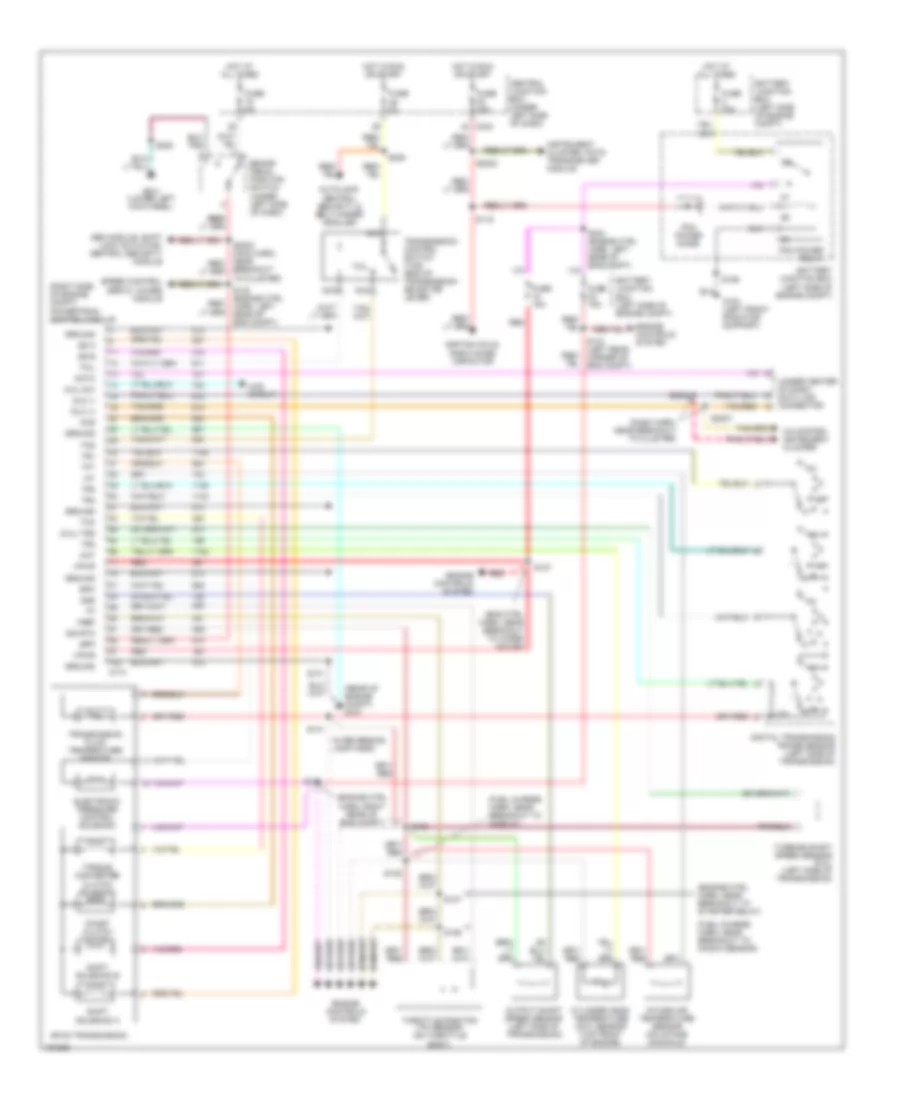
5.4L, A/T Wiring Diagram, 4R100 for Ford Expedition 2002
List of elements for 5.4L, A/T Wiring Diagram, 4R100 for Ford Expedition 2002:
- (5.4l)
- (dash harn, near breakout to cluster)
- (eng ctrl harn, near breakout to wiper motor)
- (engine ctrl harn, near breakout to starter relay)
- (engine ctrl harn, right rear of eng compt)
- (fuel charge harn, near breakout to ho2s 21)
- (fuel charge harn, near breakout to knock sensor)
- (in reversing lamp harn)
- (rear of engine compt) g101
- (right side of engine compt) powertrain control module
- (under center of dash) data link connector
- 4r100 transmission
- 4wd circuit
- 4x4 low
- A/c system, instrument cluster
- Autolamp, central security & belt minder modules
- Battery junction box (left side of engine compt)
- Bpp
- Brake pedal position switch (under left side of dash)
- Breakout to cluster)
- C174
- C243
- Ccs
- Central junction box (under left side of dash)
- Cht
- Coast clutch control
- Cylinder head temperature (cht) sensor (top front of engine)
- Data
- Digital transmission range sensor (left side of transmission)
- Dlc (+)
- Dlc (-)
- Electronic pressure control solenoid
- Engine controls system
- Epc
- Fuse 15a
- Fuse 30a
- Fuse 5a
- G104 (left front radiator support)
- G201 (lower left kick panel)
- Gem module, shift lock actuator, central security module
- Ground
- Hot at all times
- Hot in run or start
- Iat
- Ignition coils, radio noise capacitor
- Instrument cluster, pats transceiver module
- Intake air temperature sensor (on intake manifold)
- Nca
- Oss
- Output shaft speed sensor (left side of transmission)
- Pcm power diode
- Pcm power relay
- R p
- Red
- S101
- S106
- S116
- S127
- S130 (engine ctrl harn, left rear of eng compt)
- S134 (left rear corner of eng compt)
- S135
- S136
- S137
- S138
- S140
- S141
- S160 (engine ctrl harn, left rear of eng compt)
- S2002
- S2007
- S2008
- S208
- S225
- Shift solenoid a
- Shift solenoid b
- Sig rtn
- Speed control servo, 4wabs module
- Ss a
- Ss b
- Tcc
- Tcil
- Tcs
- Tft
- Throttle position (tp) sensor (on throttle body)
- Torque converter clutch solenoid
- Tr1
- Tr2
- Tr3
- Tr4
- Transmission control switch (tcs) (end of transmission selector lever)
- Transmission fluid temperature sensor
- Tss
- Turbine shaft speed sensor (5.4l) (left side of transmission)
- Vpwr
- Vref