TRANSMISSION
4WD Wiring Diagram for Ford Expedition 2004

List of elements for 4WD Wiring Diagram for Ford Expedition 2004:
- (behind left kick panel)
- (on left "b" pillar, behind trim) g300
- 4wd sw
- A/c clutch relay
- Abs control module (at left side of engine compt)
- Air suspension module
- Awd
- C135
- C175b
- C270b
- C270k
- C270m
- C3184a
- C3184b
- Can bus +
- Can bus -
- Central junction box (behind right kick panel)
- Computer data lines system
- Datalink connector (under left side of dash)
- Diff lock sol
- Four wheel drive control module (at left "b"pillar)
- Four-wheel drive switch
- Fuse 10a
- Fuse 30a
- G301
- Ground
- High
- Hot at all times
- Illum
- Integrated wheel ends solenoid (at right rear of eng compt)
- Interior lights system
- Low
- Magnetic clutch coil
- N tow sw
- Off
- Pcm sig
- Position a
- Position b
- Position c
- Position d
- Powertrain control module (on right side of firewall)
- Red
- S113
- S346
- S349 (body main harn, near g301 breakout)
- S357
- Sig return
- Signal rtn
- Solenoid
- Transfer case
- Transfer case assembly
- Ubp diag
- Vbatt
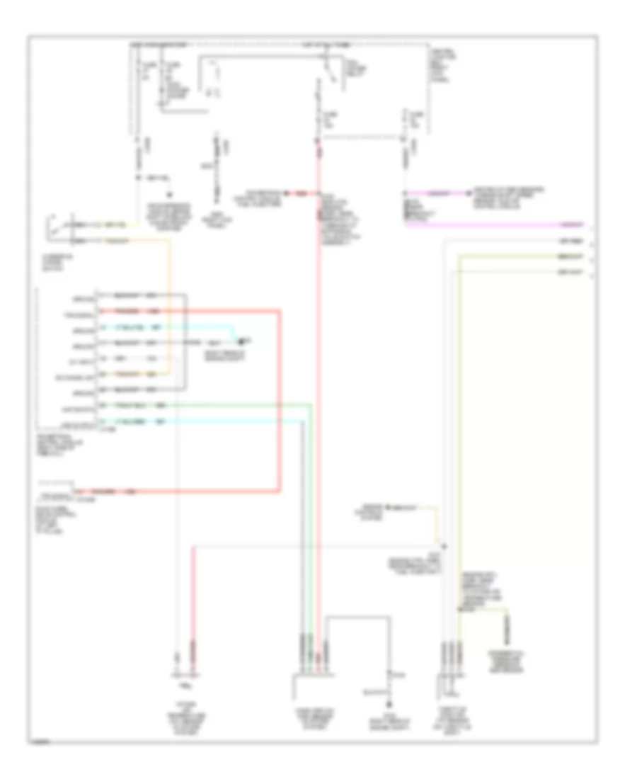
A/T Wiring Diagram (1 of 2) for Ford Expedition 2004
List of elements for A/T Wiring Diagram (1 of 2) for Ford Expedition 2004:
- (engine crtl harn, near breakout to intake air temperature sensor) s125
- (right rear of engine compt)
- Air suspension module, brake shift interlock & electronic compass
- C175b
- C270a
- C270b
- C270f
- C3184b
- Central junction box (right kick panel)
- Differential pressure feedback egr sensor
- Engine controls system
- Four wheel drive control module (at left "p" pillar)
- Fuse
- Fuse 15a
- G102
- G102 (right rear of engine compt)
- G200 (right kick panel)
- Ground
- Heated oxygen sensors, turbine shaft speed sensor, idle air control module
- Hot at all times
- Hot in run or start
- Iat input
- Intake air temperature (iat) sensor (in intake system)
- Maf output
- Maf sig rtn
- Mass airflow (maf) sensor (in intake system)
- Nca
- Od cancel sw
- Overdrive cancel switch
- Pcm power diode
- Pcm power relay
- Powertrain control module (right side of firewall)
- Powertrain control module, fuel injectors
- Red
- S108
- S109 (eng ctrl sensor red harn, near breakout to thermostat expansion valve switch assembly)
- S127 (engine ctrl harn, near breakout to fuel injector 7)
- S203
- Throttle position (tp) sensor (on throttle body)
- Tps signal
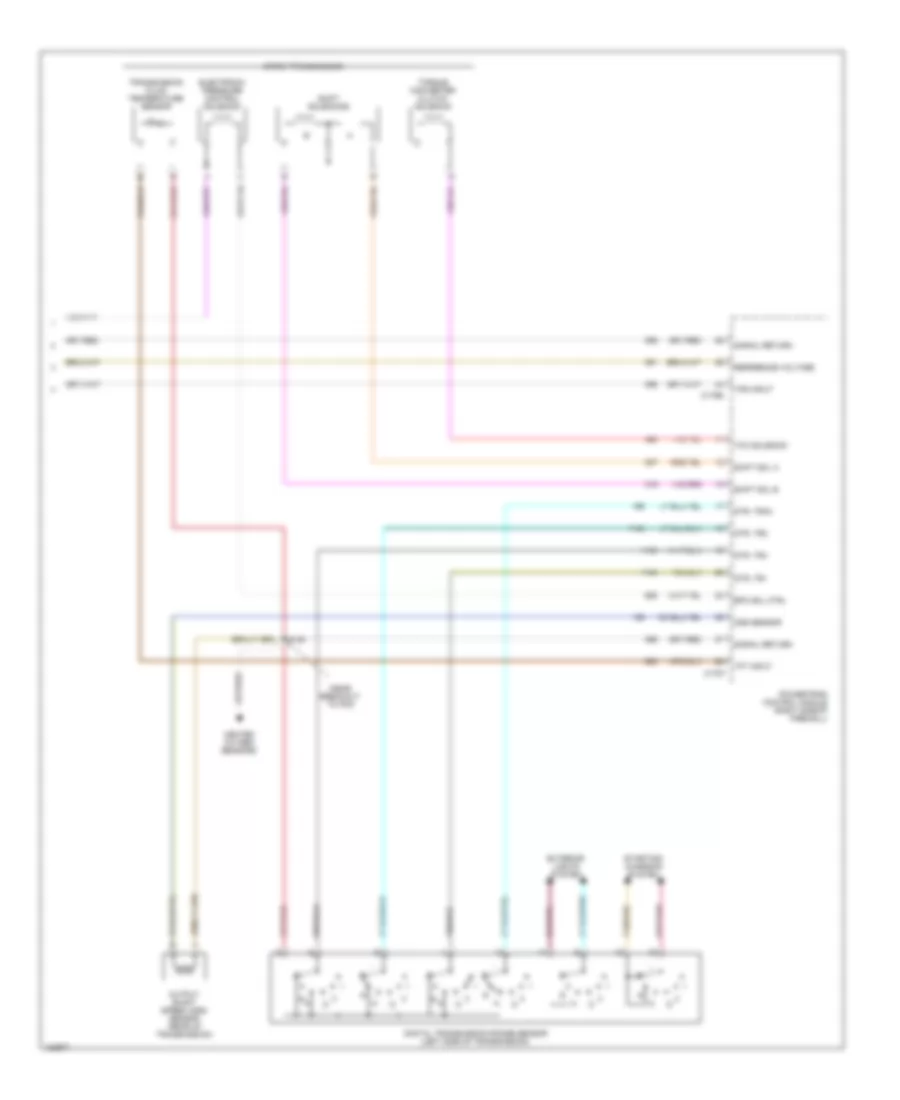
A/T Wiring Diagram (2 of 2) for Ford Expedition 2004
List of elements for A/T Wiring Diagram (2 of 2) for Ford Expedition 2004:
- (near breakout to pcm
- 4r70w transmission
- C175e
- C175t
- Digital transmission range sensor (left side of transmission)
- Dtr, tr1
- Dtr, tr2
- Dtr, tr3a
- Dtr, tr4
- Electronic pressure control solenoid
- Epc sol ctrl
- Exterior lights system
- Heated oxygen sensors
- Oss sensor
- Output shaft speed (oss) sensor (rear of transmission)
- Powertrain control module (right side of firewall)
- R n
- Reference voltage
- S138
- Shift sol a
- Shift sol b
- Shift solenoids
- Signal return
- Starting/ charging system
- Tan/red
- Tcc solenoid
- Tft input
- Torque converter clutch solenoid
- Tps input
- Transmission fluid temperature sensor