TRANSMISSION
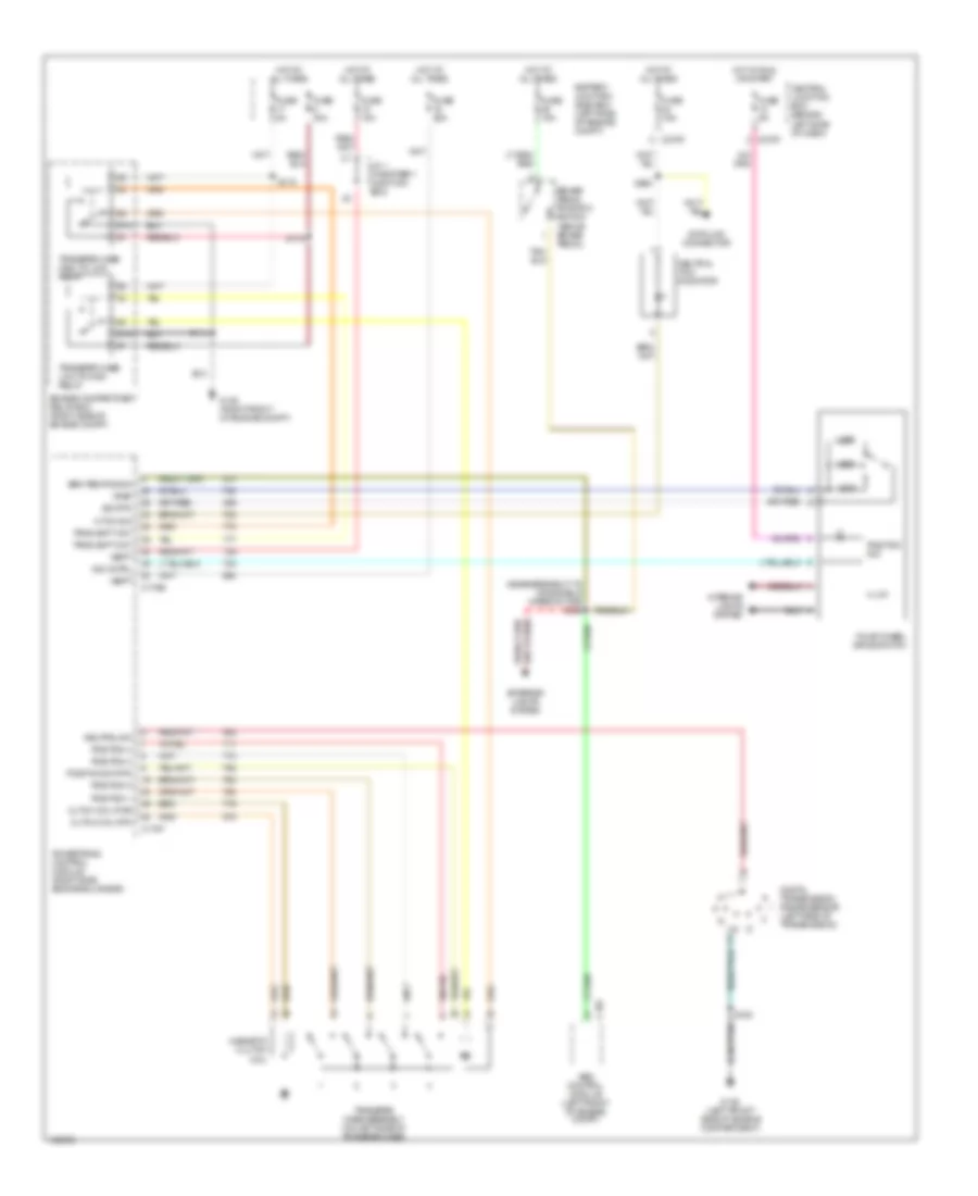
4WD Wiring Diagram, with IVD for Ford Explorer 2004

List of elements for 4WD Wiring Diagram, with IVD for Ford Explorer 2004:
4WD Wiring Diagram, without IVD for Ford Explorer 2004
List of elements for 4WD Wiring Diagram, without IVD for Ford Explorer 2004:
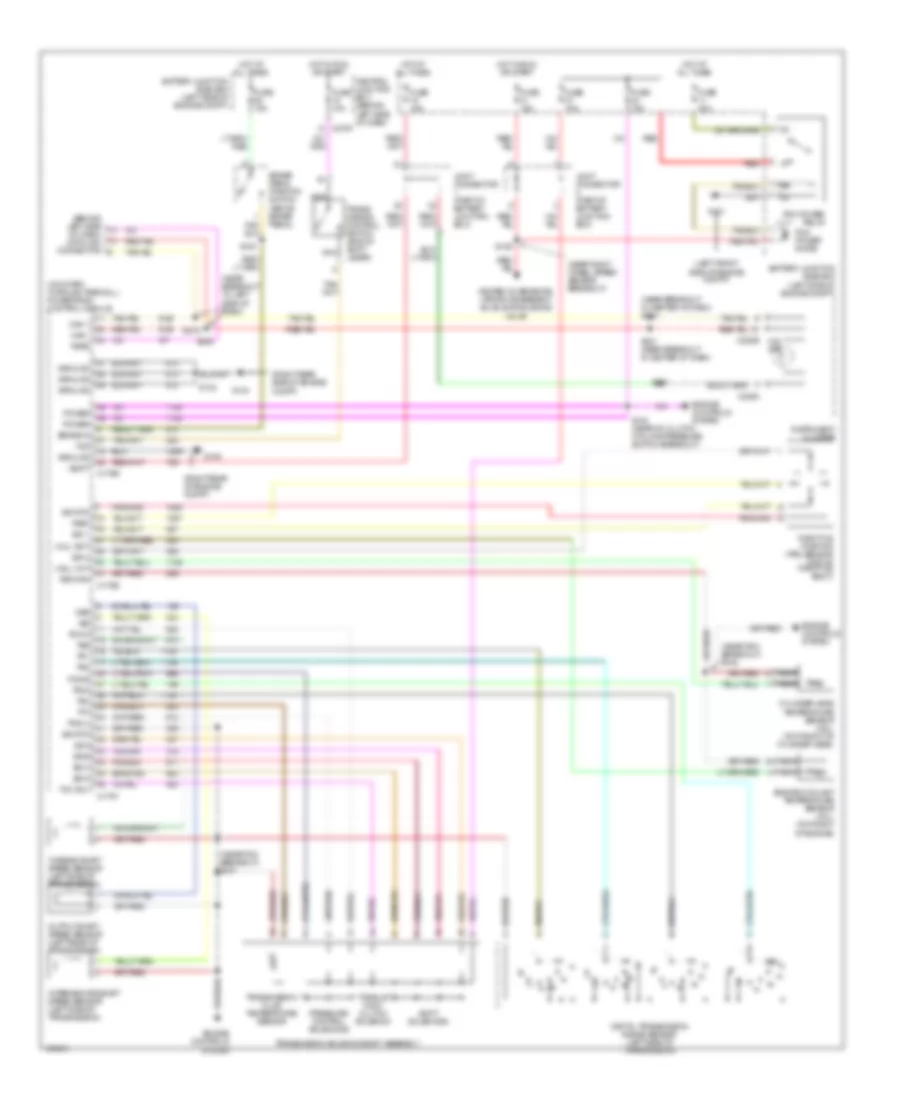
A/T Wiring Diagram for Ford Explorer 2004
List of elements for A/T Wiring Diagram for Ford Explorer 2004: