TRANSMISSION
4WD Wiring Diagram for Ford Explorer 2005

List of elements for 4WD Wiring Diagram for Ford Explorer 2005:
- (in dash panel to engine harness, near breakout to right side of engine compt)
- (main harness, near breakout to c2126) s263
- 87a
- Battery junction (bjb) box (left side of engine compt, at fender apron)
- Brake pedal position switch (above brake pedal)
- Brk ped pos sw
- C175b
- C175t
- C270f
- Central junction box (cjb) (behind left side of dash)
- Cltch coil pwr
- Cltch coil rtn
- Computer data lines system
- Digital transmission range (dtr) sensor (lower left side of automatic transmission)
- Engine compartment relay box (right side of engine compt)
- Four-wheel drive switch
- Fuse 15a
- Fuse 20a
- Fuse 30a
- Fuse 5a
- G102 (left front of engine compartment)
- G103 (right front of engine compt)
- High
- Hot at all times
- Hot in run or start
- Illum
- Ind cntrl
- Interior lights system
- Low
- Magnetic clutch coil
- N tow sw
- Nca
- Neutral sw
- Neutral tow indicator
- Off
- Other
- Position 1
- Position 2
- Position 3
- Position 4
- Position ind
- Position sw rtn
- Powertrain control module (pcm) (at right side engine bulkhead)
- S114
- S116
- S119
- S120 (w/ivd: in dash panel to engine harness, near breakout to left horn) (w/o ivd: in dash panel to engine harness, near breakout to windshield wiper motor)
- S149
- Sig rtn
- To engine harness, near breakout to g100)
- Transfer case assembly controls (on left side of transfer case)
- Transfer case high to low relay
- Transfer case low to high relay
- Trns shft mot
- Vbatt
- Vref
- W/ 1 speed
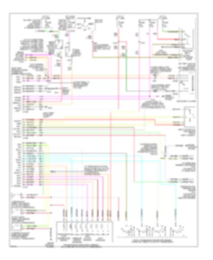
A/T Wiring Diagram for Ford Explorer 2005
List of elements for A/T Wiring Diagram for Ford Explorer 2005:
- (4.0l)
- (4.6l)
- (behind left side of dash) data link connector
- (dlc)
- (in dash panel to engine harness, near breakout to a/c clutch cycling pressure switch)
- (in dash panel to engine harness, near breakout to c1168)
- (in engine control sensor & fuel charge harness, near breakout to powertrain control module)
- (in transmission control selector neutral switch harness, near breakout to powertrain control module)
- (main harness, near breakout central to junction box)
- (main harness, near breakout to left side of dash)
- (right rear of engine compt)
- (right side engine bulkhead) powertrain control module (pcm)
- (w/ ivd: in dash panel to engine harness, near breakout to left horn) (w/o ivd: in dash panel to engine harness, near breakout to windshield wiper motor)
- (window regulator jumper harness, near breakout for center of dash)
- Acc
- Battery junction (bjb) box (left engine compt, at fender apron)
- Battery junction (bjb) box (left side of engine compt, at fender apron)
- Brake in
- Brake pedal position switch (above brake pedal)
- C175b
- C175e
- C175t
- C220a
- C220b
- C270f
- Can +
- Can -
- Central junction box (cjb) (behind left side of dash)
- Cht
- Cylinder head temperature sensor (4.6l) (top front of cylinder head)
- Digital transmission range (dtr) sensor (lower left side of automatic transmission)
- Ect
- Engine controls system
- Engine coolant temperature sensor (4.0l) (top right of engine, near injector harness)
- Feps
- Fuse 15a
- Fuse 40a
- Fuse 5a
- G101 (left front engine compt)
- G104
- G105
- Ground
- Hot at all times
- Hot in run or start
- Ignition switch
- Instrument cluster
- Intermediate shaft speed (iss) sensor (top left side of automatic transmission)
- Iss
- Lock
- Microprocessor
- Nca
- O/d off
- Off
- Oss
- Output shaft speed (oss) sensor (left rear of automatic transmission)
- Pcm power diode
- Pcm power relay
- Pcs a
- Pcs b
- Pcs c
- Power
- Pressure control solenoids
- Red
- Return
- S101
- S102
- S120
- S130
- S132
- S148
- S149
- S173
- S207 (in main harness, near breakout to central junction box)
- S209
- S212
- S232
- S301
- S304
- Shift solenoids
- Sig 1
- Sig 2
- Sig rtn
- Ss a
- Ss b
- Ss c
- Ss d
- Start
- Tcc sol
- Tcs
- Tft
- Throttle position (tps) sensor (top of throttle body)
- Torque conv clutch solenoid
- Tr1
- Tr2
- Tr3a
- Tr4
- Trans- mission control switch
- Transmission fluid temperature sensor
- Transmission solenoid body assembly (on lower left of automatic transmission)
- Tss
- Turbine shaft speed (tss) sensor (on top left side of automatic transmission)
- Vbatt
- Vref
 English