TRANSMISSION
2.0L
2.0L, A/T Wiring Diagram for Ford Explorer 2012

List of elements for 2.0L, A/T Wiring Diagram for Ford Explorer 2012:
- (battery cable wiring assembly, near breakout to 6f35 transmission)
- (not used)
- (under left front of center console)
- Battery junction box (bjb) (left rear of engine compt)
- Body control module (left end of dash)
- Brake shift interlock (under center console)
- C1381b
- C139
- C1520a
- C1520b
- C212
- C2280b
- C237
- Case gnd
- Cbb90
- Center stack assembly switch
- Cet05
- Cet06
- Cet07
- Cet08
- Cet09
- Cet10
- Cet18
- Cet25
- Cet32
- Cet34
- Cet40
- Computer data lines system
- Fuse 10a
- Fuse 15a
- Fuse 7.5a
- G103 (left front corner of engine compt)
- G200
- Gd120
- Hot at all times
- Hot in start or run
- Hs can +
- Hs can -
- I can+
- I can-
- Instrument panel cluster (ipc)
- Interior lights system
- Le111
- Lpc
- Nca
- Oss
- Oss tr gnd
- Oss/tr vpwr
- Powertrain control module (pcm) (center rear of engine compt)
- Pwr gnd
- R/s
- Ret24
- S105
- S106
- S107
- S132
- S202
- S210 (main wiring harness,near breakout to joint connector 6 (hs-can))
- Sbb56
- Sig rtn
- Ssa
- Ssb
- Ssc
- Ssd
- Sse
- Start/run
- Stt-d
- Stt-u
- Tcc
- Tft
- Tft sig rtn
- Tftin
- Tftout/ sigrtn
- Tow haul switch
- Tows
- Tr-p
- Transmission
- Transmission control module (tcm) (left side of engine compt)
- Trgnd
- Trs
- Trsw-pn
- Tspc
- Tss
- Tss gnd
- Tss vpwr
- Tss/oss
- Vbatt
- Vdb04
- Vdb05
- Vet26
- Vet27
- Vet33
3.5L
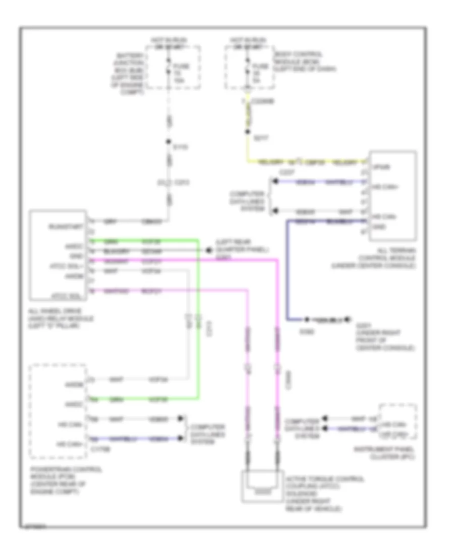
3.5L, 4WD Wiring Diagram for Ford Explorer 2012
List of elements for 3.5L, 4WD Wiring Diagram for Ford Explorer 2012:
- (left rear quarter panel) g301
- Active torque control coupling (atcc) solenoid (under right rear of vehicle)
- All terrain control module (under center console)
- All wheel drive (awd) relay module (left "d" pillar)
- Atcc sol+
- Atcc sol-
- Awdc
- Awdm
- Battery junction box (bjb) (left side of engine compt)
- Body control module (bcm) (left end of dash)
- C175b
- C213
- C2280b
- C237
- C3049
- Cbk03
- Cbp35
- Ccf21
- Computer data lines system
- Fuse 10a
- Fuse 5a
- G201 (under right front of center console)
- Gd214
- Gd349
- Gnd
- Hot in run or start
- Hs can+
- Hs can-
- Instrument panel cluster (ipc)
- Nca
- Powertrain control module (pcm) (center rear of engine compt)
- Rcf21
- Run/start
- S113
- S217
- S392
- Vcf34
- Vcf35
- Vdb04
- Vdb05
- Vpwr
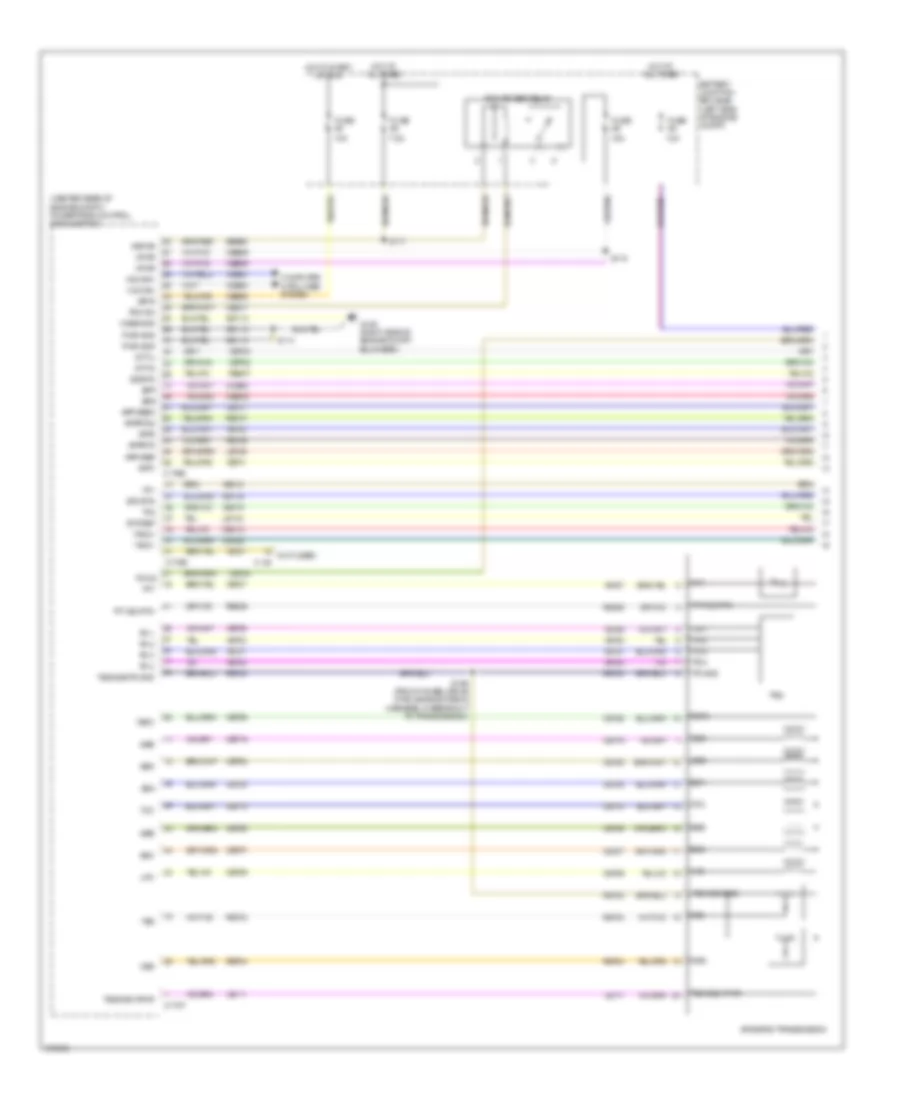
3.5L, A/T Wiring Diagram (1 of 2) for Ford Explorer 2012
List of elements for 3.5L, A/T Wiring Diagram (1 of 2) for Ford Explorer 2012:
- (center rear of engine compt) powertrain control module (pcm)
- (not used)
- 10a
- 15a
- 6f50/6f55 transmission
- 7.5a
- App1
- App2
- Apprtn
- Apprtn2
- Appvref
- Appvref2
- Battery junction box (bjb) (left side of engine compt)
- Bpp
- Bps
- C140
- C175b
- C175e
- C175t
- Case gnd
- Cbb69
- Cbb90
- Ccb08
- Ce237
- Ce412
- Ce426
- Ces09
- Cet05
- Cet06
- Cet07
- Cet08
- Cet09
- Cet10
- Cet19
- Cet25
- Cet34
- Cet42
- Cet43
- Computer data lines system
- Etcref
- Etcrtn
- Fuse
- G106 (right side of engine compt bulkhead)
- Gd113
- Hot at all times
- Hot in start or run
- Hs can+
- Hs can-
- Isp-r
- Kapwr
- Le111
- Le134
- Le136
- Le137
- Lpc
- Oss
- Pcm power relay
- Pcm rc
- Pwr gnd
- Re134
- Re136
- Re137
- Re406
- Re407
- Ret04
- Ret24
- Ret33
- S114
- S115
- S117
- S159 (front wheel drive (fwd) engine wiring harness, in breakout to transmission)
- Sbb86
- Sigrtn
- Ssa
- Ssb
- Ssc
- Ssd
- Sse
- Stt-d
- Stt-u
- Tacm+
- Tacm-
- Tcc
- Tft
- Tft sig rtn
- Tows
- Tp1
- Tp2
- Tr gnd
- Tr-1
- Tr-2
- Tr-3
- Tr-4
- Trs
- Tspc
- Tss
- Tss/oss gnd
- Tss/oss vpwr
- Tss/oss/tr gnd
- Vdb04
- Vdb05
- Ve701
- Ve702
- Ve818
- Ve819
- Vet27
- Vet29
- Vet30
- Vet31
- Vet32
- Vpwr
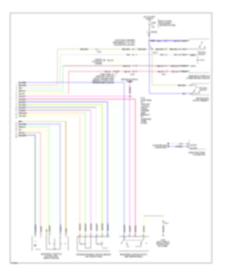
3.5L, A/T Wiring Diagram (2 of 2) for Ford Explorer 2012
List of elements for 3.5L, A/T Wiring Diagram (2 of 2) for Ford Explorer 2012:
- (dash panel to headlamp junction wiring harness, near breakout to anti-lock brake system module)
- (main wiring harness, near breakout to joint
- Accelerator pedal position sensor (left side of dash)
- Body control module (bcm) (left end of dash)
- Brake pedal position switch (above brake pedal)
- Brake shift interlock (under center console)
- C140
- C212
- C2280b
- C237
- Center stack switch assembly
- Computer data lines system
- Connector 6 (hs-can))
- Electronic throttle control (etc) (rear of engine)
- Engine controls system
- Fuse 7.5a
- G106 (right side of engine compt bulkhead)
- Hot in start or run
- Hs can+
- Hs can-
- Instrument panel cluster (ipc)
- Nca
- S112 (dash panel to headlamp junction wiring harness, near breakout to windshield wiper motor)
- S114
- S143
- S202
- S210
- Sst-d
- Sst-u
- Tow haul switch