TRANSMISSION
3.5L TURBO
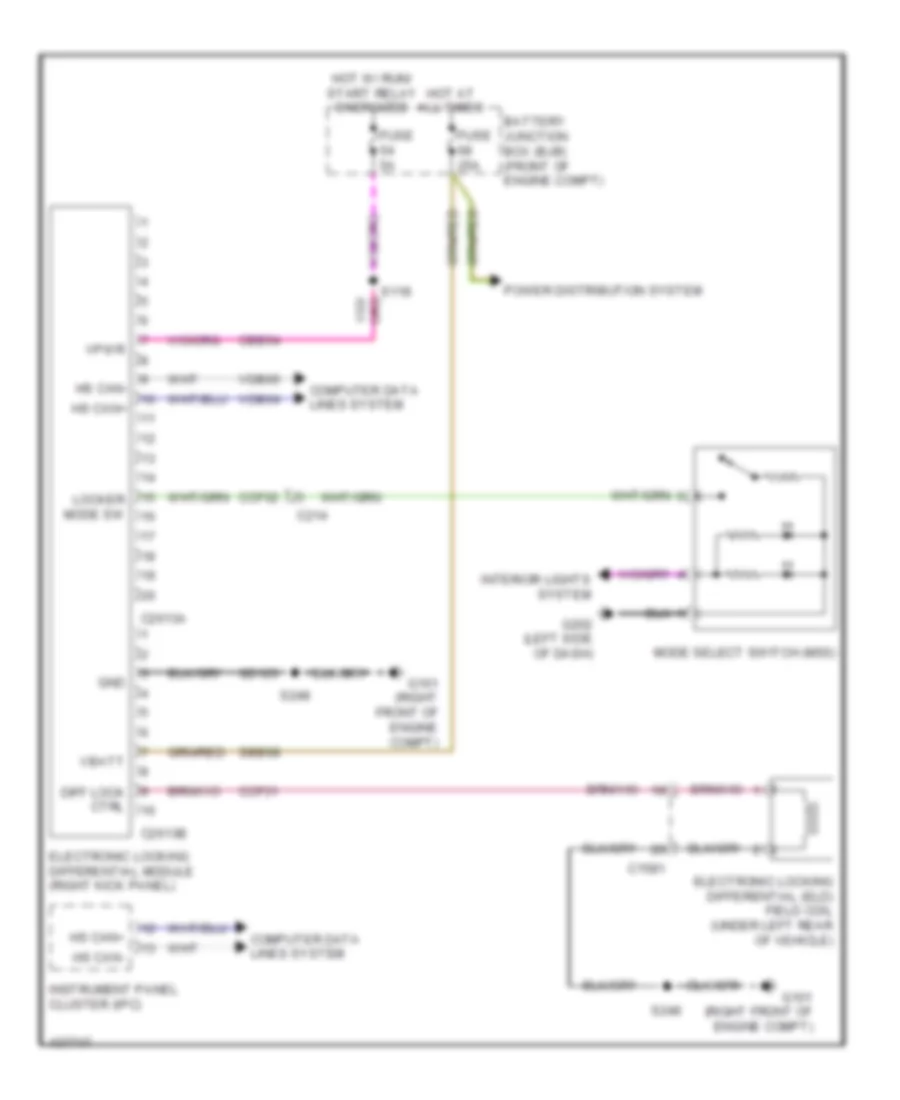
3.5L Turbo, 2WD Wiring Diagram for Ford F-150 XLT 2014

List of elements for 3.5L Turbo, 2WD Wiring Diagram for Ford F-150 XLT 2014:
- Battery junction box (bjb) (front of engine compt)
- C1581
- C214
- C2613a
- C2613b
- Cbb54
- Ccf31
- Ccf32
- Computer data lines system
- Diff lock ctrl
- Electronic locking differential (eld) field coil (under left rear of vehicle)
- Electronic locking differential module (right kick panel)
- Fuse 25a
- Fuse 5a
- G101 (right front of engine compt)
- G202 (left side of dash)
- Gd123
- Gnd
- Hot at all times
- Hot w/ run/ start relay energized
- Hs can+
- Hs can-
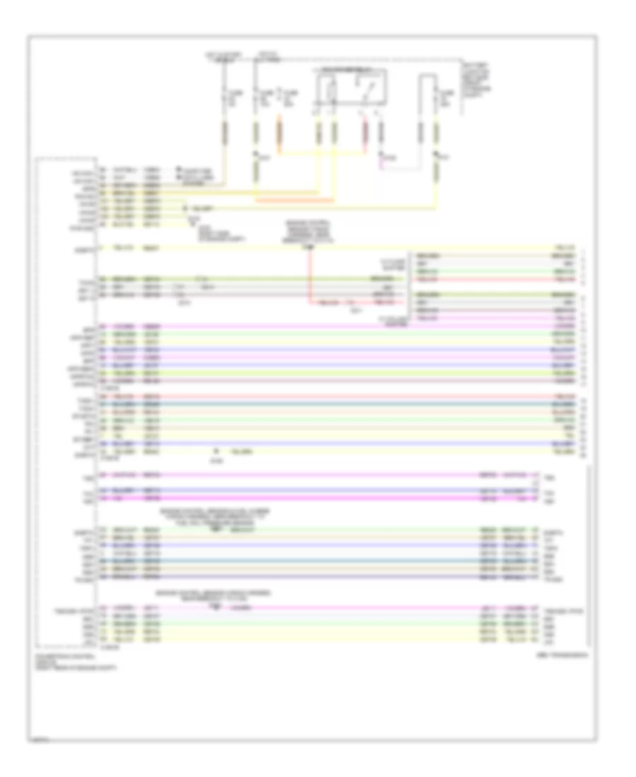
- Instrument panel cluster (ipc)
- Interior lights system
- Locker mode sw
- Mode select switch (mss)
- Power distribution system
- S118
- S248
- Sbb68
- Vbatt
- Vdb04
- Vdb05
- Vpwr
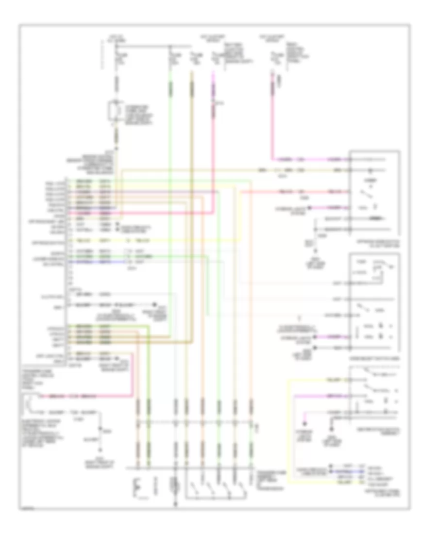
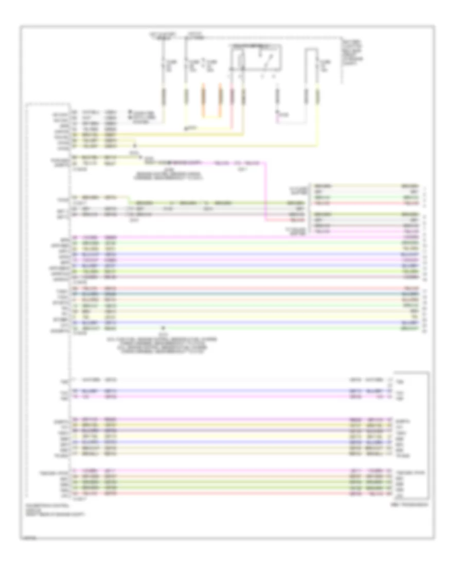
3.5L Turbo, A/T Wiring Diagram (1 of 2) for Ford F-150 XLT 2014
List of elements for 3.5L Turbo, A/T Wiring Diagram (1 of 2) for Ford F-150 XLT 2014:
- (engine control sensor & fuel charge wiring harness, near breakout to fuel rail pressure sensor) s173
- (engine control sensor wiring harness, near breakout to c110) s167
- (engine control sensor wiring harness, near breakout to c180) s104
- 6r80 transmission
- App1
- App2
- Apprtn
- Apprtn2
- Appvref
- Appvref2
- Battery junction box (bjb) (front of engine compt)
- Bpp
- Bps
- C1551b
- C1551e
- C210
- C211
- C214
- Cbb53
- Cbb75
- Ccb08
- Ce412
- Ce426
- Ce607
- Ces09
- Cet05
- Cet06
- Cet07
- Cet08
- Cet09
- Cet10
- Cet16
- Cet25
- Cet34
- Cet42
- Cet43
- Cht
- Computer data lines system
- Etcref
- Etcrtn
- Fuse 10a
- Fuse 25a
- Fuse 50a
- Fuse 5a
- G100 (right side of engine compt)
- Gd113
- Hot at all times
- Hot in start or run
- Hs can+
- Hs can-
- Ispr
- Le111
- Le134
- Le136
- Le137
- Lpc
- Oss
- Pcm power relay
- Pcm rc
- Powertrain control module (right rear of engine compt)
- Pwr gnd
- Re134
- Re136
- Re137
- Re405
- Re407
- Re454
- Ret04
- Ret24
- Ret33
- S101
- S103
- S121
- S125
- S128
- Sigrtn
- Ssa
- Ssb
- Ssc
- Ssd
- Sse
- Sst d
- Sst u
- Tacm+
- Tacm-
- Tcc
- Tft
- Tows
- Tp1
- Tp2
- Tr gnd
- Trp
- Tspc
- Tss
- Tss/oss vpwr
- Vdb04
- Vdb05
- Ve701
- Ve702
- Ve712
- Ve818
- Ve819
- Vet27
- Vet32
- Vpwr
- W/ column shifter
- W/ floor shifter
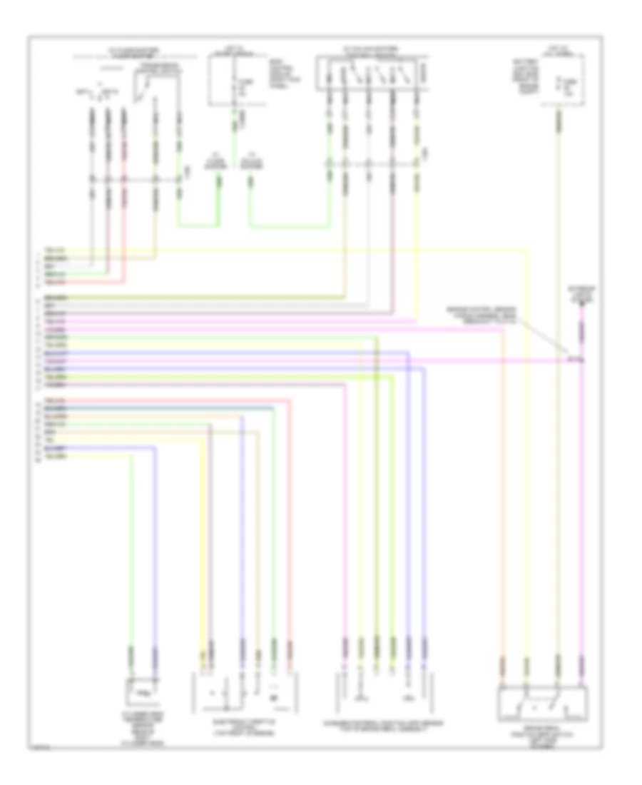
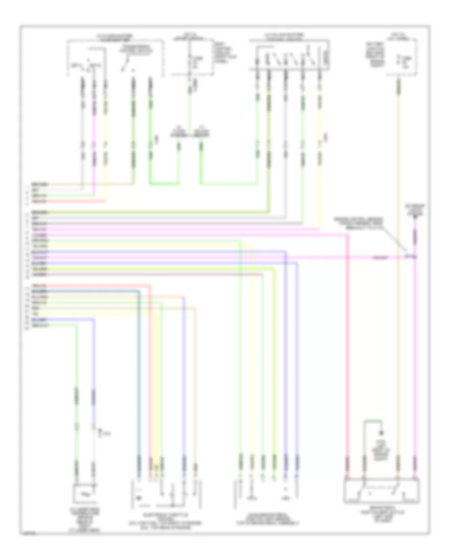
3.5L Turbo, A/T Wiring Diagram (2 of 2) for Ford F-150 XLT 2014
List of elements for 3.5L Turbo, A/T Wiring Diagram (2 of 2) for Ford F-150 XLT 2014:
- (engine control sensor wiring harness, near breakout to c110)
- (w/ column shifter)
- (w/ floor shifter) floor shifter
- Accelerator pedal position (app) sensor (top of brake pedal assembly)
- Battery junction box (bjb) (front of engine compt)
- Body control module (right kick panel)
- Brake pedal position (bpp) switch (left side of dash)
- C2280b
- C264
- C329
- Cylinder head temperature sensor (rear of right cylinder head)
- Electronic throttle control (top front of engine)
- Exterior lights system
- Fuse 10a
- Fuse 5a
- Hot at all times
- Hot in start or run
- Nca
- R/s
- S112
- Sigrtn
- Sst d
- Sst u
- Sst-d
- Sst-u
- Tow haul switch
- Tows
- Transmission control switch
- W/ coluum shifter
- W/ floor shifter
3.5L Turbo, AWD Wiring Diagram for Ford F-150 XLT 2014
List of elements for 3.5L Turbo, AWD Wiring Diagram for Ford F-150 XLT 2014:
- 2 hi
- 4 hi
- 4 lo
- Amber
- Battery junction box (bjb) (front of engine compt)
- Body control module (right kick panel)
- C140
- C1581
- C214
- C2280b
- C2371a
- C2371b
- C329
- Cbb54
- Ccf01
- Ccf03
- Ccf05
- Ccf07
- Ccf08
- Ccf11
- Ccf13
- Ccf14
- Ccf15
- Ccf16
- Ccf17
- Ccf31
- Ccf32
- Center stack switch assembly
- Clutch coil
- Clutch solenoid
- Computer data lines system
- Diff lock ctrl
- Electronic locking differential (eld) field coil (w/ electronically locking differential) (under left rear of vehicle)
- Fuse 10a
- Fuse 20a
- Fuse 25a
- Fuse 5a
- G101 (right front of engine compt)
- G202 (left side of dash)
- G203 (left side of dash)
- Gd123
- Gnd 1
- Gnd 2
- Green
- Hi to low
- Hill descent
- Hot at all times
- Hot in start or run
- Hs can +
- Hs can -
- Hs can+
- Hs can-
- Instrument panel cluster (ipc)
- Integrated wheel end (iwe) solenoid (left side of engine compt)
- Interior lights system
- Iwe ctrl
- Locker mode sw
- Low to hi
- Mode select switch (mss)
- Mtr-ccw
- Mtr-cw
- Off road easy led
- Off road switch
- Off-road mode switch (w/ svt raptor)
- Pos 1
- Pos 1 mtr
- Pos 2
- Pos 2 mtr
- Pos 3
- Pos 3 mtr
- Pos 4
- Pos 4 mtr
- Pos rtn
- Rcf09
- Rcf13
- S118
- S172 (engine control sensor wiring harness, in breakout to integrated wheel end solenoid)
- S248
- S248 (w/ electronically locking differential)
- S329
- Ssb20
- Ssb68
- Sw cntral
- Swrtn
- Tcs on/off
- Transfer case assembly (left rear of transmission)
- Transfer case control module (tccm) (right kick panel)
- Vbatt
- Vdb04
- Vdb05
- Vpwr
- W/ electronically locking differential
3.7L CNG
3.7L CNG, 2WD Wiring Diagram for Ford F-150 XLT 2014
List of elements for 3.7L CNG, 2WD Wiring Diagram for Ford F-150 XLT 2014:
- Battery junction box (bjb) (front of engine compt)
- C1581
- C214
- C2613a
- C2613b
- Cbb54
- Ccf31
- Ccf32
- Computer data lines system
- Diff lock ctrl
- Electronic locking differential (eld) field coil (under left rear of vehicle)
- Electronic locking differential module (right kick panel)
- Fuse 25a
- Fuse 5a
- G101 (right front of engine compt)
- G202 (left side of dash)
- Gd123
- Gnd
- Hot at all times
- Hot w/ run/ start relay energized
- Hs can+
- Hs can-
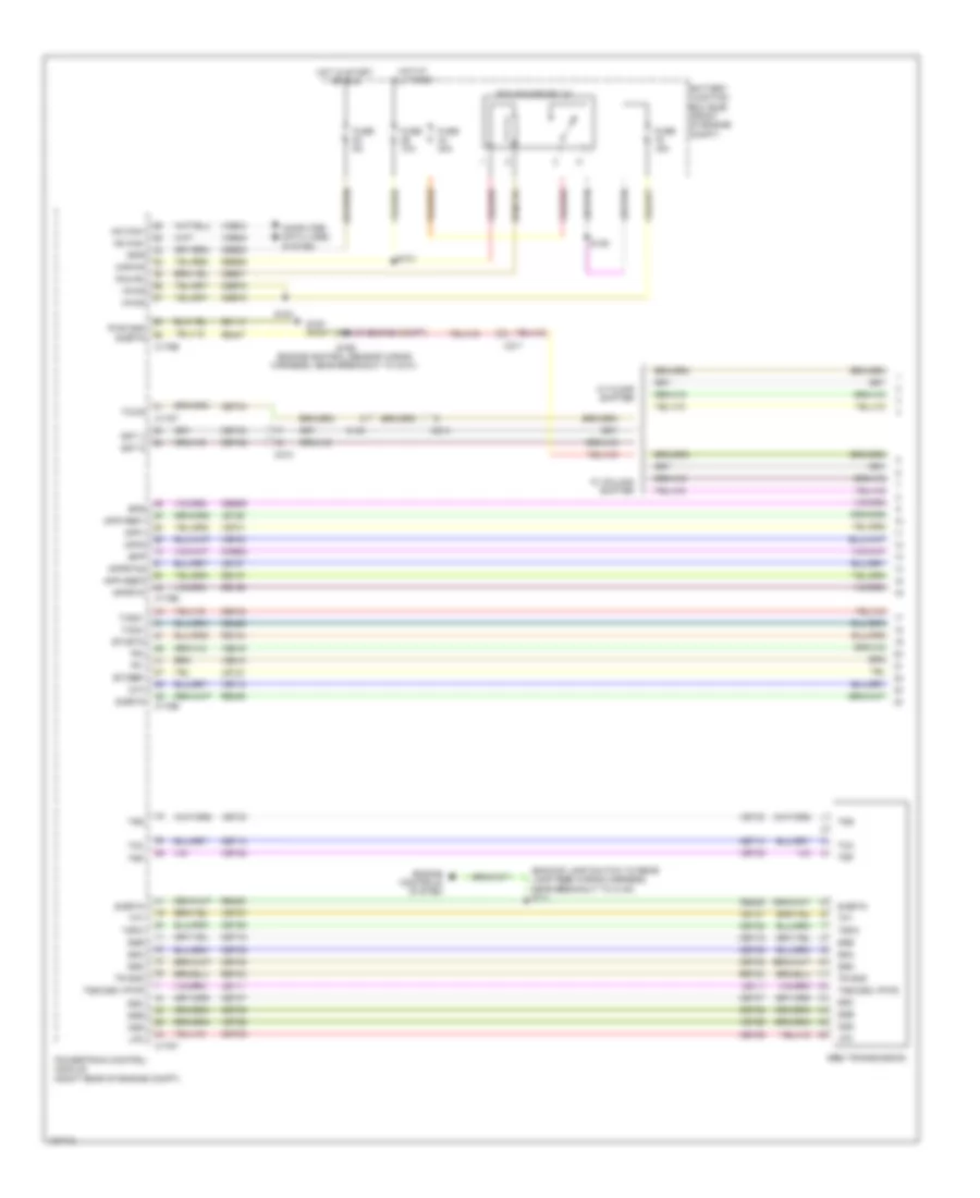
- Instrument panel cluster (ipc)
- Interior lights system
- Locker mode sw
- Mode select switch (mss)
- Power distribution system
- S118
- S248
- Sbb68
- Vbatt
- Vdb04
- Vdb05
- Vpwr
3.7L CNG, A/T Wiring Diagram (1 of 2) for Ford F-150 XLT 2014
List of elements for 3.7L CNG, A/T Wiring Diagram (1 of 2) for Ford F-150 XLT 2014:
- (backup lamp switch to rear lamp feed wiring harness, near breakout to c140) s111
- 6r80 transmission
- App1
- App2
- Apprtn
- Apprtn2
- Appvref1
- Appvref2
- Battery junction box (bjb) (front of engine compt)
- Bpp
- Bps
- C140
- C175b
- C175e
- C175t
- C210
- C211
- C214
- Cbb53
- Cbb75
- Ccb08
- Ce412
- Ce426
- Ce607
- Ces09
- Cet05
- Cet06
- Cet07
- Cet08
- Cet09
- Cet10
- Cet18
- Cet25
- Cet34
- Cet42
- Cet43
- Cht
- Computer data lines system
- Engine controls system
- Etcref
- Etcrtn
- Fuse 10a
- Fuse 15a
- Fuse 40a
- Fuse 5a
- G100 (right side of engine compt)
- Gd113
- Hot at all times
- Hot in start or run
- Hs can+
- Hs can-
- Ispr
- Kapwr
- Le111
- Le134
- Le136
- Le137
- Lpc
- Oss
- Pcm power relay
- Pcm rc
- Powertrain control module (right rear of engine compt)
- Pwr gnd
- Re134
- Re136
- Re137
- Re405
- Re407
- Ret24
- S101
- S103
- S125
- S169 (engine control sensor wiring harness, near breakout to g101)
- Sbb26
- Sigrtn
- Ssa
- Ssb
- Ssc
- Ssd
- Sse
- Sst d
- Sst u
- Tacm+
- Tacm-
- Tcc
- Tft
- Tows
- Tp1
- Tp2
- Tr gnd
- Trp
- Tspc
- Tss
- Tss/oss vpwr
- Vdb04
- Vdb05
- Ve701
- Ve702
- Ve712
- Ve818
- Ve819
- Vet26
- Vet27
- Vet32
- Vet33
- Vpwr
- W/ column shifter
- W/ floor shifter
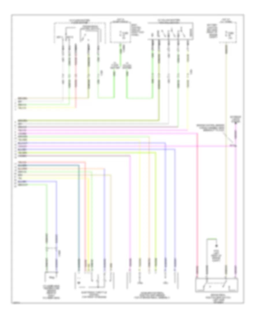
3.7L CNG, A/T Wiring Diagram (2 of 2) for Ford F-150 XLT 2014
List of elements for 3.7L CNG, A/T Wiring Diagram (2 of 2) for Ford F-150 XLT 2014:
- (engine control sensor wiring harness, near breakout to c110)
- (w/ column shifter)
- (w/ floor shifter) floor shifter
- Accelerator pedal position (app) sensor (top of brake pedal assembly)
- Battery junction box (bjb) (front of engine compt)
- Body control module (right kick panel)
- Brake pedal position (bpp) switch (left side of dash)
- C1026
- C2280b
- C264
- C329
- Cylinder head temperature sensor (rear of right cylinder head)
- Electronic throttle control (top front of engine)
- Exterior lights system
- Fuse 10a
- Fuse 5a
- G102 (left front of engine compt)
- Hot at all times
- Hot in start or run
- Nca
- R/s
- S112
- Sigrtn
- Sst d
- Sst u
- Sst-d
- Sst-u
- Tow haul switch
- Tows
- Transmission control switch
- W/ column shifter
- W/ floor shifter
3.7L CNG, AWD Wiring Diagram for Ford F-150 XLT 2014
List of elements for 3.7L CNG, AWD Wiring Diagram for Ford F-150 XLT 2014:
- 2 hi
- 4 hi
- 4 lo
- Amber
- Battery junction box (bjb) (front of engine compt)
- Body control module (right kick panel)
- C140
- C1581
- C214
- C2280b
- C2371a
- C2371b
- C329
- Cbb54
- Ccf01
- Ccf03
- Ccf05
- Ccf07
- Ccf08
- Ccf11
- Ccf13
- Ccf14
- Ccf15
- Ccf16
- Ccf17
- Ccf31
- Ccf32
- Center stack switch assembly
- Clutch coil
- Clutch solenoid
- Computer data lines system
- Diff lock ctrl
- Electronic locking differential (eld) field coil (w/ electronically locking differential) (under left rear of vehicle)
- Fuse 10a
- Fuse 20a
- Fuse 25a
- Fuse 5a
- G101 (right front of engine compt)
- G202 (left side of dash)
- G203 (left side of dash)
- Gd123
- Gnd 1
- Gnd 2
- Green
- Hi to low
- Hill descent
- Hot at all times
- Hot in start or run
- Hs can +
- Hs can -
- Hs can+
- Hs can-
- Instrument panel cluster (ipc)
- Integrated wheel end (iwe) solenoid (left side of engine compt)
- Interior lights system
- Iwe ctrl
- Locker mode sw
- Low to hi
- Mode select switch (mss)
- Mtr-ccw
- Mtr-cw
- Off road easy led
- Off road switch
- Off-road mode switch (w/ svt raptor)
- Pos 1
- Pos 1 mtr
- Pos 2
- Pos 2 mtr
- Pos 3
- Pos 3 mtr
- Pos 4
- Pos 4 mtr
- Pos rtn
- Rcf09
- Rcf13
- S118
- S172 (engine control sensor wiring harness, in breakout to integrated wheel end solenoid)
- S248
- S248 (w/ electronically locking differential)
- S329
- Ssb20
- Ssb68
- Sw cntral
- Swrtn
- Tcs on/off
- Transfer case assembly (left rear of transmission)
- Transfer case control module (tccm) (right kick panel)
- Vbatt
- Vdb04
- Vdb05
- Vpwr
- W/ electronically locking differential
3.7L FLEX FUEL
3.7L Flex Fuel, 2WD Wiring Diagram for Ford F-150 XLT 2014
List of elements for 3.7L Flex Fuel, 2WD Wiring Diagram for Ford F-150 XLT 2014:
- Battery junction box (bjb) (front of engine compt)
- C1581
- C214
- C2613a
- C2613b
- Cbb54
- Ccf31
- Ccf32
- Computer data lines system
- Diff lock ctrl
- Electronic locking differential (eld) field coil (under left rear of vehicle)
- Electronic locking differential module (right kick panel)
- Fuse 25a
- Fuse 5a
- G101 (right front of engine compt)
- G202 (left side of dash)
- Gd123
- Gnd
- Hot at all times
- Hot w/ run/ start relay energized
- Hs can+
- Hs can-
- Instrument panel cluster (ipc)
- Interior lights system
- Locker mode sw
- Mode select switch (mss)
- Power distribution system
- S118
- S248
- Sbb68
- Vbatt
- Vdb04
- Vdb05
- Vpwr
3.7L Flex Fuel, A/T Wiring Diagram (1 of 2) for Ford F-150 XLT 2014
List of elements for 3.7L Flex Fuel, A/T Wiring Diagram (1 of 2) for Ford F-150 XLT 2014:
- (backup lamp switch to rear lamp feed wiring harness, near breakout to c140) s111
- 6r80 transmission
- App1
- App2
- Apprtn
- Apprtn2
- Appvref1
- Appvref2
- Battery junction box (bjb) (front of engine compt)
- Bpp
- Bps
- C140
- C175b
- C175e
- C175t
- C210
- C211
- C214
- Cbb53
- Cbb75
- Ccb08
- Ce412
- Ce426
- Ce607
- Ces09
- Cet05
- Cet06
- Cet07
- Cet08
- Cet09
- Cet10
- Cet18
- Cet25
- Cet34
- Cet42
- Cet43
- Cht
- Computer data lines system
- Engine controls system
- Etcref
- Etcrtn
- Fuse 10a
- Fuse 15a
- Fuse 40a
- Fuse 5a
- G100 (right side of engine compt)
- Gd113
- Hot at all times
- Hot in start or run
- Hs can+
- Hs can-
- Ispr
- Kapwr
- Le111
- Le134
- Le136
- Le137
- Lpc
- Oss
- Pcm power relay
- Pcm rc
- Powertrain control module (right rear of engine compt)
- Pwr gnd
- Re134
- Re136
- Re137
- Re405
- Re407
- Ret24
- S101
- S103
- S125
- S169 (engine control sensor wiring harness, near breakout to g101)
- Sbb26
- Sigrtn
- Ssa
- Ssb
- Ssc
- Ssd
- Sse
- Sst d
- Sst u
- Tacm+
- Tacm-
- Tcc
- Tft
- Tows
- Tp1
- Tp2
- Tr gnd
- Trp
- Tspc
- Tss
- Tss/oss vpwr
- Vdb04
- Vdb05
- Ve701
- Ve702
- Ve712
- Ve818
- Ve819
- Vet26
- Vet27
- Vet32
- Vet33
- Vpwr
- W/ column shifter
- W/ floor shifter
3.7L Flex Fuel, A/T Wiring Diagram (2 of 2) for Ford F-150 XLT 2014
List of elements for 3.7L Flex Fuel, A/T Wiring Diagram (2 of 2) for Ford F-150 XLT 2014:
- (engine control sensor wiring harness, near breakout to c110)
- (w/ column shifter)
- (w/ floor shifter) floor shifter
- Accelerator pedal position (app) sensor (top of brake pedal assembly)
- Battery junction box (bjb) (front of engine compt)
- Body control module (right kick panel)
- Brake pedal position (bpp) switch (left side of dash)
- C1026
- C2280b
- C264
- C329
- Cylinder head temperature sensor (rear of right cylinder head)
- Electronic throttle control (top front of engine)
- Exterior lights system
- Fuse 10a
- Fuse 5a
- G102 (left front of engine compt)
- Hot at all times
- Hot in start or run
- Nca
- R/s
- S112
- Sigrtn
- Sst d
- Sst u
- Sst-d
- Sst-u
- Tow haul switch
- Tows
- Transmission control switch
- W/ column shifter
- W/ floor shifter
3.7L Flex Fuel, AWD Wiring Diagram for Ford F-150 XLT 2014
List of elements for 3.7L Flex Fuel, AWD Wiring Diagram for Ford F-150 XLT 2014:
- 2 hi
- 4 hi
- 4 lo
- Amber
- Battery junction box (bjb) (front of engine compt)
- Body control module (right kick panel)
- C140
- C1581
- C214
- C2280b
- C2371a
- C2371b
- C329
- Cbb54
- Ccf01
- Ccf03
- Ccf05
- Ccf07
- Ccf08
- Ccf11
- Ccf13
- Ccf14
- Ccf15
- Ccf16
- Ccf17
- Ccf31
- Ccf32
- Center stack switch assembly
- Clutch coil
- Clutch solenoid
- Computer data lines system
- Diff lock ctrl
- Electronic locking differential (eld) field coil (w/ electronically locking differential) (under left rear of vehicle)
- Fuse 10a
- Fuse 20a
- Fuse 25a
- Fuse 5a
- G101 (right front of engine compt)
- G202 (left side of dash)
- G203 (left side of dash)
- Gd123
- Gnd 1
- Gnd 2
- Green
- Hi to low
- Hill descent
- Hot at all times
- Hot in start or run
- Hs can +
- Hs can -
- Hs can+
- Hs can-
- Instrument panel cluster (ipc)
- Integrated wheel end (iwe) solenoid (left side of engine compt)
- Interior lights system
- Iwe ctrl
- Locker mode sw
- Low to hi
- Mode select switch (mss)
- Mtr-ccw
- Mtr-cw
- Off road easy led
- Off road switch
- Off-road mode switch (w/ svt raptor)
- Pos 1
- Pos 1 mtr
- Pos 2
- Pos 2 mtr
- Pos 3
- Pos 3 mtr
- Pos 4
- Pos 4 mtr
- Pos rtn
- Rcf09
- Rcf13
- S118
- S172 (engine control sensor wiring harness, in breakout to integrated wheel end solenoid)
- S248
- S248 (w/ electronically locking differential)
- S329
- Ssb20
- Ssb68
- Sw cntral
- Swrtn
- Tcs on/off
- Transfer case assembly (left rear of transmission)
- Transfer case control module (tccm) (right kick panel)
- Vbatt
- Vdb04
- Vdb05
- Vpwr
- W/ electronically locking differential
3.7L LPG
3.7L LPG, 2WD Wiring Diagram for Ford F-150 XLT 2014
List of elements for 3.7L LPG, 2WD Wiring Diagram for Ford F-150 XLT 2014:
- Battery junction box (bjb) (front of engine compt)
- C1581
- C214
- C2613a
- C2613b
- Cbb54
- Ccf31
- Ccf32
- Computer data lines system
- Diff lock ctrl
- Electronic locking differential (eld) field coil (under left rear of vehicle)
- Electronic locking differential module (right kick panel)
- Fuse 25a
- Fuse 5a
- G101 (right front of engine compt)
- G202 (left side of dash)
- Gd123
- Gnd
- Hot at all times
- Hot w/ run/ start relay energized
- Hs can+
- Hs can-
- Instrument panel cluster (ipc)
- Interior lights system
- Locker mode sw
- Mode select switch (mss)
- Power distribution system
- S118
- S248
- Sbb68
- Vbatt
- Vdb04
- Vdb05
- Vpwr
3.7L LPG, A/T Wiring Diagram (1 of 2) for Ford F-150 XLT 2014
List of elements for 3.7L LPG, A/T Wiring Diagram (1 of 2) for Ford F-150 XLT 2014:
- (backup lamp switch to rear lamp feed wiring harness, near breakout to c140) s111
- 6r80 transmission
- App1
- App2
- Apprtn
- Apprtn2
- Appvref1
- Appvref2
- Battery junction box (bjb) (front of engine compt)
- Bpp
- Bps
- C140
- C175b
- C175e
- C175t
- C210
- C211
- C214
- Cbb53
- Cbb75
- Ccb08
- Ce412
- Ce426
- Ce607
- Ces09
- Cet05
- Cet06
- Cet07
- Cet08
- Cet09
- Cet10
- Cet18
- Cet25
- Cet34
- Cet42
- Cet43
- Cht
- Computer data lines system
- Engine controls system
- Etcref
- Etcrtn
- Fuse 10a
- Fuse 15a
- Fuse 40a
- Fuse 5a
- G100 (right side of engine compt)
- Gd113
- Hot at all times
- Hot in start or run
- Hs can+
- Hs can-
- Ispr
- Kapwr
- Le111
- Le134
- Le136
- Le137
- Lpc
- Oss
- Pcm power relay
- Pcm rc
- Powertrain control module (right rear of engine compt)
- Pwr gnd
- Re134
- Re136
- Re137
- Re405
- Re407
- Ret24
- S101
- S103
- S125
- S169 (engine control sensor wiring harness, near breakout to g101)
- Sbb26
- Sigrtn
- Ssa
- Ssb
- Ssc
- Ssd
- Sse
- Sst d
- Sst u
- Tacm+
- Tacm-
- Tcc
- Tft
- Tows
- Tp1
- Tp2
- Tr gnd
- Trp
- Tspc
- Tss
- Tss/oss vpwr
- Vdb04
- Vdb05
- Ve701
- Ve702
- Ve712
- Ve818
- Ve819
- Vet26
- Vet27
- Vet32
- Vet33
- Vpwr
- W/ column shifter
- W/ floor shifter
3.7L LPG, A/T Wiring Diagram (2 of 2) for Ford F-150 XLT 2014
List of elements for 3.7L LPG, A/T Wiring Diagram (2 of 2) for Ford F-150 XLT 2014:
- (engine control sensor wiring harness, near breakout to c110)
- (w/ column shifter)
- (w/ floor shifter) floor shifter
- Accelerator pedal position (app) sensor (top of brake pedal assembly)
- Battery junction box (bjb) (front of engine compt)
- Body control module (right kick panel)
- Brake pedal position (bpp) switch (left side of dash)
- C1026
- C2280b
- C264
- C329
- Cylinder head temperature sensor (rear of right cylinder head)
- Electronic throttle control (top front of engine)
- Exterior lights system
- Fuse 10a
- Fuse 5a
- G102 (left front of engine compt)
- Hot at all times
- Hot in start or run
- Nca
- R/s
- S112
- Sigrtn
- Sst d
- Sst u
- Sst-d
- Sst-u
- Tow haul switch
- Tows
- Transmission control switch
- W/ column shifter
- W/ floor shifter
3.7L LPG, AWD Wiring Diagram for Ford F-150 XLT 2014
List of elements for 3.7L LPG, AWD Wiring Diagram for Ford F-150 XLT 2014:
- 2 hi
- 4 hi
- 4 lo
- Amber
- Battery junction box (bjb) (front of engine compt)
- Body control module (right kick panel)
- C140
- C1581
- C214
- C2280b
- C2371a
- C2371b
- C329
- Cbb54
- Ccf01
- Ccf03
- Ccf05
- Ccf07
- Ccf08
- Ccf11
- Ccf13
- Ccf14
- Ccf15
- Ccf16
- Ccf17
- Ccf31
- Ccf32
- Center stack switch assembly
- Clutch coil
- Clutch solenoid
- Computer data lines system
- Diff lock ctrl
- Electronic locking differential (eld) field coil (w/ electronically locking differential) (under left rear of vehicle)
- Fuse 10a
- Fuse 20a
- Fuse 25a
- Fuse 5a
- G101 (right front of engine compt)
- G202 (left side of dash)
- G203 (left side of dash)
- Gd123
- Gnd 1
- Gnd 2
- Green
- Hi to low
- Hill descent
- Hot at all times
- Hot in start or run
- Hs can +
- Hs can -
- Hs can+
- Hs can-
- Instrument panel cluster (ipc)
- Integrated wheel end (iwe) solenoid (left side of engine compt)
- Interior lights system
- Iwe ctrl
- Locker mode sw
- Low to hi
- Mode select switch (mss)
- Mtr-ccw
- Mtr-cw
- Off road easy led
- Off road switch
- Off-road mode switch (w/ svt raptor)
- Pos 1
- Pos 1 mtr
- Pos 2
- Pos 2 mtr
- Pos 3
- Pos 3 mtr
- Pos 4
- Pos 4 mtr
- Pos rtn
- Rcf09
- Rcf13
- S118
- S172 (engine control sensor wiring harness, in breakout to integrated wheel end solenoid)
- S248
- S248 (w/ electronically locking differential)
- S329
- Ssb20
- Ssb68
- Sw cntral
- Swrtn
- Tcs on/off
- Transfer case assembly (left rear of transmission)
- Transfer case control module (tccm) (right kick panel)
- Vbatt
- Vdb04
- Vdb05
- Vpwr
- W/ electronically locking differential
5.0L FLEX FUEL
5.0L Flex Fuel, 2WD Wiring Diagram for Ford F-150 XLT 2014
List of elements for 5.0L Flex Fuel, 2WD Wiring Diagram for Ford F-150 XLT 2014:
- Battery junction box (bjb) (front of engine compt)
- C1581
- C214
- C2613a
- C2613b
- Cbb54
- Ccf31
- Ccf32
- Computer data lines system
- Diff lock ctrl
- Electronic locking differential (eld) field coil (under left rear of vehicle)
- Electronic locking differential module (right kick panel)
- Fuse 25a
- Fuse 5a
- G101 (right front of engine compt)
- G202 (left side of dash)
- Gd123
- Gnd
- Hot at all times
- Hot w/ run/ start relay energized
- Hs can+
- Hs can-
- Instrument panel cluster (ipc)
- Interior lights system
- Locker mode sw
- Mode select switch (mss)
- Power distribution system
- S118
- S248
- Sbb68
- Vbatt
- Vdb04
- Vdb05
- Vpwr
5.0L Flex Fuel, A/T Wiring Diagram (1 of 2) for Ford F-150 XLT 2014
List of elements for 5.0L Flex Fuel, A/T Wiring Diagram (1 of 2) for Ford F-150 XLT 2014:
- (5.0l flex fuel: engine control sensor & fuel charge wiring harness, near breakout to c1019) (6.2l: engine control sensor & fuel charge wiring harness, near breakout to c133)
- 6r80 transmission
- App1
- App2
- Apprtn
- Apprtn2
- Appvref
- Appvref2
- Battery junction box (bjb) (front of engine compt)
- Bpp
- Bps
- C1381b
- C1381e
- C1381t
- C140
- C210
- C211
- C214
- Cbb53
- Cbb75
- Ccb08
- Ce412
- Ce426
- Ce607
- Ces09
- Cet05
- Cet06
- Cet07
- Cet08
- Cet09
- Cet10
- Cet18
- Cet25
- Cet34
- Cet42
- Cet43
- Cht
- Computer data lines system
- E-sigrtn
- Etcref
- Etcrtn
- Fuse 10a
- Fuse 15a
- Fuse 40a
- Fuse 5a
- G100 (right side of engine compt)
- Gd113
- Hot at all times
- Hot in start or run
- Hs can+
- Hs can-
- Ispr
- Kapwr
- Le111
- Le134
- Le136
- Le137
- Lpc
- Oss
- Pcm power relay
- Pcm rc
- Powertrain control module (right rear of engine compt)
- Pwr gnd
- Re134
- Re136
- Re137
- Re405
- Re406
- Re407
- Ret24
- S101
- S103
- S125
- S169 (engine control sensor wiring harness, near breakout to g101)
- S173
- Sbb26
- Sigrtn
- Ssa
- Ssb
- Ssc
- Ssd
- Sse
- Sst d
- Sst u
- Tacm+
- Tacm-
- Tcc
- Tft
- Tows
- Tp1
- Tp2
- Tr gnd
- Trp
- Tspc
- Tss
- Tss/oss vpwr
- Vdb04
- Vdb05
- Ve701
- Ve702
- Ve712
- Ve818
- Ve819
- Vet26
- Vet27
- Vet32
- Vet33
- Vpwr
- W/ column shifter
- W/ floor shifter
5.0L Flex Fuel, A/T Wiring Diagram (2 of 2) for Ford F-150 XLT 2014
List of elements for 5.0L Flex Fuel, A/T Wiring Diagram (2 of 2) for Ford F-150 XLT 2014:
- (engine control sensor wiring harness, near breakout to c110)
- (w/ column shifter)
- (w/ floor shifter) floor shifter
- 6.2l
- Accelerator pedal position (app) sensor (top of brake pedal assembly)
- Battery junction box (bjb) (front of engine compt)
- Body control module (right kick panel)
- Brake pedal position (bpp) switch (left side of dash)
- C133
- C2280b
- C264
- C329
- Cylinder head temperature sensor (rear of right cylinder head)
- Electronic throttle control (5.0l flex fuel: top front of engine) (6.2l: top rear of engine)
- Exterior lights system
- Fuse 10a
- Fuse 5a
- G102 (left front of engine compt)
- Hot at all times
- Hot in start or run
- Nca
- R/s
- S112
- Sigrtn
- Sst d
- Sst u
- Sst-d
- Sst-u
- Tow haul switch
- Tows
- Transmission control switch
- W/ column shifter
- W/ floor shifter
5.0L Flex Fuel, AWD Wiring Diagram for Ford F-150 XLT 2014
List of elements for 5.0L Flex Fuel, AWD Wiring Diagram for Ford F-150 XLT 2014:
- 2 hi
- 4 hi
- 4 lo
- Amber
- Battery junction box (bjb) (front of engine compt)
- Body control module (right kick panel)
- C140
- C1581
- C214
- C2280b
- C2371a
- C2371b
- C329
- Cbb54
- Ccf01
- Ccf03
- Ccf05
- Ccf07
- Ccf08
- Ccf11
- Ccf13
- Ccf14
- Ccf15
- Ccf16
- Ccf17
- Ccf31
- Ccf32
- Center stack switch assembly
- Clutch coil
- Clutch solenoid
- Computer data lines system
- Diff lock ctrl
- Electronic locking differential (eld) field coil (w/ electronically locking differential) (under left rear of vehicle)
- Fuse 10a
- Fuse 20a
- Fuse 25a
- Fuse 5a
- G101 (right front of engine compt)
- G202 (left side of dash)
- G203 (left side of dash)
- Gd123
- Gnd 1
- Gnd 2
- Green
- Hi to low
- Hill descent
- Hot at all times
- Hot in start or run
- Hs can +
- Hs can -
- Hs can+
- Hs can-
- Instrument panel cluster (ipc)
- Integrated wheel end (iwe) solenoid (left side of engine compt)
- Interior lights system
- Iwe ctrl
- Locker mode sw
- Low to hi
- Mode select switch (mss)
- Mtr-ccw
- Mtr-cw
- Off road easy led
- Off road switch
- Off-road mode switch (w/ svt raptor)
- Pos 1
- Pos 1 mtr
- Pos 2
- Pos 2 mtr
- Pos 3
- Pos 3 mtr
- Pos 4
- Pos 4 mtr
- Pos rtn
- Rcf09
- Rcf13
- S118
- S172 (engine control sensor wiring harness, in breakout to integrated wheel end solenoid)
- S248
- S248 (w/ electronically locking differential)
- S329
- Ssb20
- Ssb68
- Sw cntral
- Swrtn
- Tcs on/off
- Transfer case assembly (left rear of transmission)
- Transfer case control module (tccm) (right kick panel)
- Vbatt
- Vdb04
- Vdb05
- Vpwr
- W/ electronically locking differential
6.2L
6.2L, 2WD Wiring Diagram for Ford F-150 XLT 2014
List of elements for 6.2L, 2WD Wiring Diagram for Ford F-150 XLT 2014:
- Battery junction box (bjb) (front of engine compt)
- C1581
- C214
- C2613a
- C2613b
- Cbb54
- Ccf31
- Ccf32
- Computer data lines system
- Diff lock ctrl
- Electronic locking differential (eld) field coil (under left rear of vehicle)
- Electronic locking differential module (right kick panel)
- Fuse 25a
- Fuse 5a
- G101 (right front of engine compt)
- G202 (left side of dash)
- Gd123
- Gnd
- Hot at all times
- Hot w/ run/ start relay energized
- Hs can+
- Hs can-
- Instrument panel cluster (ipc)
- Interior lights system
- Locker mode sw
- Mode select switch (mss)
- Power distribution system
- S118
- S248
- Sbb68
- Vbatt
- Vdb04
- Vdb05
- Vpwr
6.2L, A/T Wiring Diagram (1 of 2) for Ford F-150 XLT 2014
List of elements for 6.2L, A/T Wiring Diagram (1 of 2) for Ford F-150 XLT 2014:
- (5.0l flex fuel: engine control sensor & fuel charge wiring harness, near breakout to c1019) (6.2l: engine control sensor & fuel charge wiring harness, near breakout to c133)
- 6r80 transmission
- App1
- App2
- Apprtn
- Apprtn2
- Appvref
- Appvref2
- Battery junction box (bjb) (front of engine compt)
- Bpp
- Bps
- C1381b
- C1381e
- C1381t
- C140
- C210
- C211
- C214
- Cbb53
- Cbb75
- Ccb08
- Ce412
- Ce426
- Ce607
- Ces09
- Cet05
- Cet06
- Cet07
- Cet08
- Cet09
- Cet10
- Cet18
- Cet25
- Cet34
- Cet42
- Cet43
- Cht
- Computer data lines system
- E-sigrtn
- Etcref
- Etcrtn
- Fuse 10a
- Fuse 15a
- Fuse 40a
- Fuse 5a
- G100 (right side of engine compt)
- Gd113
- Hot at all times
- Hot in start or run
- Hs can+
- Hs can-
- Ispr
- Kapwr
- Le111
- Le134
- Le136
- Le137
- Lpc
- Oss
- Pcm power relay
- Pcm rc
- Powertrain control module (right rear of engine compt)
- Pwr gnd
- Re134
- Re136
- Re137
- Re405
- Re406
- Re407
- Ret24
- S101
- S103
- S125
- S169 (engine control sensor wiring harness, near breakout to g101)
- S173
- Sbb26
- Sigrtn
- Ssa
- Ssb
- Ssc
- Ssd
- Sse
- Sst d
- Sst u
- Tacm+
- Tacm-
- Tcc
- Tft
- Tows
- Tp1
- Tp2
- Tr gnd
- Trp
- Tspc
- Tss
- Tss/oss vpwr
- Vdb04
- Vdb05
- Ve701
- Ve702
- Ve712
- Ve818
- Ve819
- Vet26
- Vet27
- Vet32
- Vet33
- Vpwr
- W/ column shifter
- W/ floor shifter
6.2L, A/T Wiring Diagram (2 of 2) for Ford F-150 XLT 2014
List of elements for 6.2L, A/T Wiring Diagram (2 of 2) for Ford F-150 XLT 2014:
- (engine control sensor wiring harness, near breakout to c110)
- (w/ column shifter)
- (w/ floor shifter) floor shifter
- 6.2l
- Accelerator pedal position (app) sensor (top of brake pedal assembly)
- Battery junction box (bjb) (front of engine compt)
- Body control module (right kick panel)
- Brake pedal position (bpp) switch (left side of dash)
- C133
- C2280b
- C264
- C329
- Cylinder head temperature sensor (rear of right cylinder head)
- Electronic throttle control (5.0l flex fuel: top front of engine) (6.2l: top rear of engine)
- Exterior lights system
- Fuse 10a
- Fuse 5a
- G102 (left front of engine compt)
- Hot at all times
- Hot in start or run
- Nca
- R/s
- S112
- Sigrtn
- Sst d
- Sst u
- Sst-d
- Sst-u
- Tow haul switch
- Tows
- Transmission control switch
- W/ column shifter
- W/ floor shifter
6.2L, AWD Wiring Diagram for Ford F-150 XLT 2014
List of elements for 6.2L, AWD Wiring Diagram for Ford F-150 XLT 2014:
- 2 hi
- 4 hi
- 4 lo
- Amber
- Battery junction box (bjb) (front of engine compt)
- Body control module (right kick panel)
- C140
- C1581
- C214
- C2280b
- C2371a
- C2371b
- C329
- Cbb54
- Ccf01
- Ccf03
- Ccf05
- Ccf07
- Ccf08
- Ccf11
- Ccf13
- Ccf14
- Ccf15
- Ccf16
- Ccf17
- Ccf31
- Ccf32
- Center stack switch assembly
- Clutch coil
- Clutch solenoid
- Computer data lines system
- Diff lock ctrl
- Electronic locking differential (eld) field coil (w/ electronically locking differential) (under left rear of vehicle)
- Fuse 10a
- Fuse 20a
- Fuse 25a
- Fuse 5a
- G101 (right front of engine compt)
- G202 (left side of dash)
- G203 (left side of dash)
- Gd123
- Gnd 1
- Gnd 2
- Green
- Hi to low
- Hill descent
- Hot at all times
- Hot in start or run
- Hs can +
- Hs can -
- Hs can+
- Hs can-
- Instrument panel cluster (ipc)
- Integrated wheel end (iwe) solenoid (left side of engine compt)
- Interior lights system
- Iwe ctrl
- Locker mode sw
- Low to hi
- Mode select switch (mss)
- Mtr-ccw
- Mtr-cw
- Off road easy led
- Off road switch
- Off-road mode switch (w/ svt raptor)
- Pos 1
- Pos 1 mtr
- Pos 2
- Pos 2 mtr
- Pos 3
- Pos 3 mtr
- Pos 4
- Pos 4 mtr
- Pos rtn
- Rcf09
- Rcf13
- S118
- S172 (engine control sensor wiring harness, in breakout to integrated wheel end solenoid)
- S248
- S248 (w/ electronically locking differential)
- S329
- Ssb20
- Ssb68
- Sw cntral
- Swrtn
- Tcs on/off
- Transfer case assembly (left rear of transmission)
- Transfer case control module (tccm) (right kick panel)
- Vbatt
- Vdb04
- Vdb05
- Vpwr
- W/ electronically locking differential