TRANSMISSION
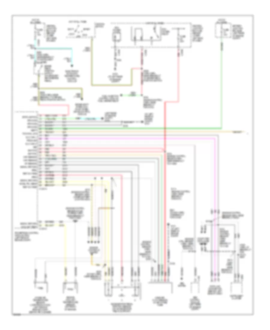
4WD Wiring Diagram for Ford F450 Super Duty 2005

List of elements for 4WD Wiring Diagram for Ford F450 Super Duty 2005:
- (engine control harn, near breakout for g100) s124
- (gasoline: left rear of engine compt) (diesel: left side of engine compt)
- (in back up lamp switch harn, near breakout to auxiliary relay box 3)
- (in main harn, near break- out to brake pedal position switch)
- (in main harn, near breakout for instrument cluster)
- (main harn, near breakout for instrument cluster) s254
- (main harn, near breakout for instrument cluster) s271
- (main harn, near breakout for restraints control module) s230
- (not used)
- 4wd hi
- 4wd hi ind
- 4wd lo
- 4wd lo ind
- 4wd sw
- 87a
- Abs control module
- Abs system
- Auxiliary relay box 3 (gasoline: left rear side of engine compt) (diesel: left side of engine compt)
- Battery
- Battery junction box (bjb) (left rear of engine compt)
- Bpp sw
- Brake pedal position switch (behind left side of dash, above brake pedal)
- C135
- C1381a neut sw sen
- C175b
- C220b
- C270a
- C270h
- C281a
- C281b
- C350a
- C350b
- Central junction box (cjb) (lower left side of dash)
- Computer data lines system
- Data link connector (behind left side of dash)
- Eatc module
- Electronic shift-on-the-fly (esof) solenoid (right side of engine compt)
- Enc gnd rtn
- Esof sol
- Esof solenoid, vacuum pump motor, drl relay
- Exterior lights system
- Four-wheel drive control module (behind right side of dash)
- Four-wheel drive switch
- Fuse 10a
- Fuse 15a
- Fuse 30a
- G201 (behind left side of dash)
- G202 (behind left side of dash)
- G300 (at floor, in left front footwell)
- Gas diesel
- Ground
- Hi to lo
- Hot at all times
- Hot in run
- Hot in run or acc
- Hot in run or start
- Ign (st/run)
- Illum
- Instrument cluster
- Instrument cluster, electrochromatic inside mirror unit, compass sensor module, clutch pedal position switch
- Instrument cluster, windshield wiper motor, fuel tank selector switch
- Interior lights system
- Iso bus
- Lo to hi
- Mtr pos 2
- Mtr pos 3
- Mtr pos 4
- Mtr pos 5
- Neut sens
- Off
- Powertrain control module (diesel: left side of engine compt) (gas: left side of firewall)
- Red
- Ref volt
- S163
- S201
- S205
- S225 (main harn, near break- out for instrument cluster)
- S228 (main harn, near breakout for instrument cluster)
- S250
- S253 (main harn, at breakout for instrument cluster)
- S257
- S259
- S268
- Shift sol
- Transfer case assembly
- Transfer case high to low relay
- Transfer case low to high relay
- Vehicle security module
- Vpwr
- Vss
- Vss out
6.0L DIESEL
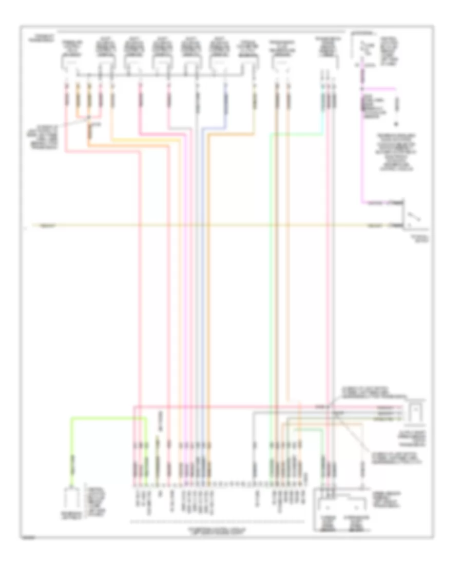
6.0L Diesel, A/T Wiring Diagram (1 of 2) for Ford F450 Super Duty 2005
List of elements for 6.0L Diesel, A/T Wiring Diagram (1 of 2) for Ford F450 Super Duty 2005:
- (at left rear of engine compt) g101
- (engine control sensor & fuel charge harn, near breakout for c1064) s192
- (engine control sensor harn,
- (engine control sensor harn, near breakout g300)
- (engine ctrl sensor harn, near breakout for c124) s115
- (left rear of engine compt) g100
- (main harn, at breakout for (dlc)) s220
- Abs control module (left rear of engine compt)
- Abs system
- Acc
- Accel pdl sens
- Accelerator pedal position sensor (on accelerator pedal support)
- Aps2
- Aps3
- Battery junction box (bjb) (left rear of engine compt)
- Brake pedal position switch (on bracket, above brake pedal)
- Brake shift interlock, four wheel drive control module
- C135
- C1381a
- C1381c
- C220a
- C270a
- C270c
- C270f
- C270h
- Central junction box (cjb) (behind lower left side of dash)
- Computer data lines system
- Coolant temp
- Data link connector (behind left side of dash)
- Dlc can h
- Dlc can l
- Electronic automatic temperature control module
- Engine controls system
- Engine coolant temperature sensor (on front of engine)
- Fuel injection control module, fuel heater relay
- Fuse 10a
- Fuse 15a
- Fuse 20a
- G100 (at left rear of engine compt)
- G101 (at left rear of engine compt)
- Ground
- Hot at all times
- Iat sensor
- Ignition
- Ignition switch
- Instrument cluster
- Intake air temperature sensor (late production) (left side of engine compt, behind air cleaner)
- Lock
- Maf sensor
- Mass air- flow sensor (in air intake tube)
- Near breakout to brake pedal position switch)
- Near breakout to c128) s150
- Near breakout to instrument cluster)
- Off
- Pcm power diode
- Pcm power relay
- Pedal position switch)
- Powertrain control module (pcm) (left side of engine compt)
- Prog sig
- Red
- Ref voltage
- Run
- S106
- S114 (engine control harn, near breakout for g101)
- S117
- S123 (engine control sensor harn, near breakout to c1298)
- S140
- S142 (engine control sensor harn, near breakout to c135)
- S162
- S170 (engine control sensor harn, under battery junction box)
- S182 (engine control harn, near breakout for g100)
- S213 (main harn, near breakout for (dlc))
- S221 (in main harn, at breakout for c2186)
- S223 (in main harn, near breakout for c218)
- Signal return
- Start
- Stoplamp sw
- Tan
- Tow/haul sw
- Vbatt
- Vss
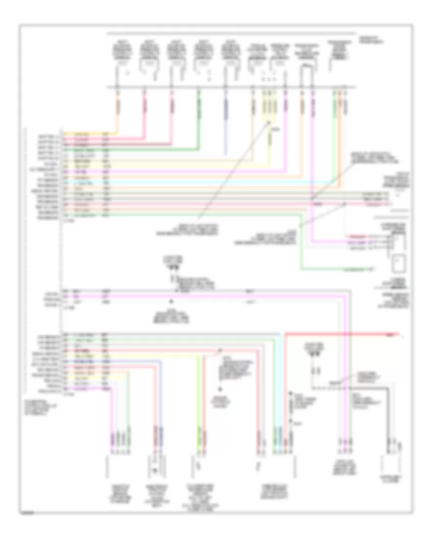
6.0L Diesel, A/T Wiring Diagram (2 of 2) for Ford F450 Super Duty 2005
List of elements for 6.0L Diesel, A/T Wiring Diagram (2 of 2) for Ford F450 Super Duty 2005:
- (in back-up lamp switch to rear lamp feed harn, near breakout for c1107)
- (in back-up light switch to rear light feed harn, near breakout for transmission)
- (not used)
- C1381b
- C270a
- Central junction box (cjb) (behind lower left side of dash)
- Fuse 15a
- Hot in run
- Intermediate shaft speed sensor
- Iss sig
- Nca
- Oss sig
- Output shaft speed sensor (top of transmission)
- Pc sol pwr
- Pc-a sol
- Powertrain control module (left side of engine compt)
- Pressure control (pc-a) solenoid
- Ref volt
- Rev lmp ctrl
- Reversing lamp relay
- S127
- S128
- S129
- S235 (main harn, near breakout to sunload sensor)
- Shift solenoid pressure control a (sspc-a)
- Shift solenoid pressure control b (sspc-b)
- Shift solenoid pressure control c (sspc-c)
- Shift solenoid pressure control d (sspc-d)
- Shift solenoid pressure control e (sspc-e)
- Sig trn
- Speed sensor assembly (left side of transmission)
- Sspc-a crl
- Sspc-b ctrl
- Sspc-c crl
- Sspc-d ctrl
- Sspc-e ctrl
- Tcc sol ctrl
- Temperature blend door actuator, function selector switch assembly, blower motor relay, electronic automatic temperature control module
- Tft sens sig
- Torqshift transmission
- Torque converter clutch solenoid
- Tow/haul switch
- Tr-p gnd
- Tr-p sig
- Transmission fluid temperature sensor
- Transmission range sensor assembly (tr-p)
- Tro
- Tss sig
- Turbine shaft speed sensor
6.8L
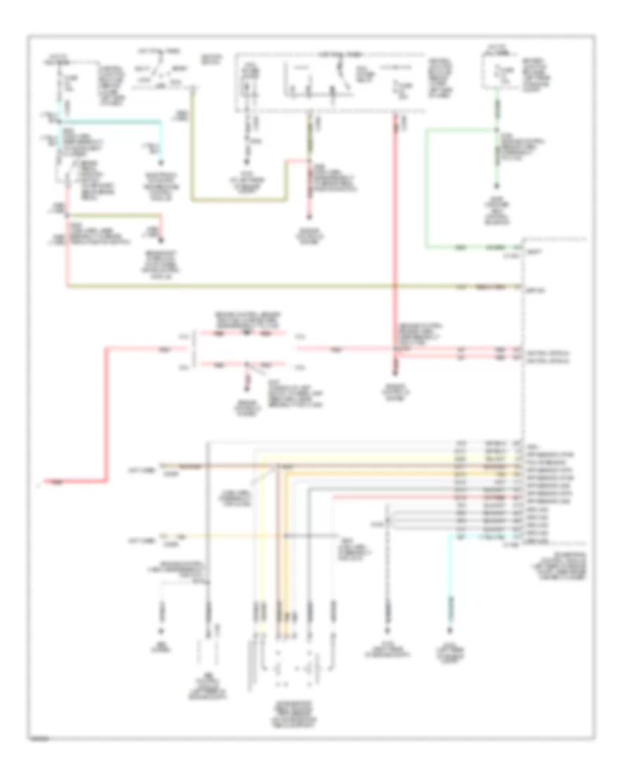
6.8L, A/T Wiring Diagram (1 of 2) for Ford F450 Super Duty 2005
List of elements for 6.8L, A/T Wiring Diagram (1 of 2) for Ford F450 Super Duty 2005:
- (back-up lamp switch to rear lamp feed harn, near breakout for c1385)
- (back-up light switch to rear light feed harn, near breakout for transmission)
- (main harn, at breakout for (dlc))
- (top of transmission) output shaft speed sensor
- Breakout for c135)
- C175a
- C175b
- C175c
- C220a
- Computer data lines system
- Cyl head temp
- Cylinder head temperature sensor (6.8l: on left cyl head) (5.4l: rear of block under intake)
- Data link connector (behind left side of dash)
- Electronic throttle control motor (on throttle body)
- Engine controls system
- Etc return
- Etc wot cntrl
- G102 (right rear of engine compt)
- Hs can +
- Hs can -
- Iat sensor
- Instrument cluster
- Intermediate shaft speed sensor
- Iss sensor
- Maf sensor
- Mass air flow (maf) sensor (left front of engine compt)
- Oss sensor
- Powertrain control module (on left side of firewall)
- Pressure control (pc-a) solenoid
- Prog sig
- Red
- Ref voltage
- S109 (engine control sensor harn, near breakout for c135)
- S127
- S128 (back-up light switch to rear light feed harn, near breakout for transmission)
- S129
- S132 (engine control sensor & fuel charge harn, near breakout for cop 7)
- S143
- S146
- S213 (main harn, near breakout to (dlc))
- S220
- Shift sol a
- Shift sol b
- Shift sol c
- Shift sol d
- Shift sol e
- Shift solenoid pressure control a (sspc-a)
- Shift solenoid pressure control b (sspc-b)
- Shift solenoid pressure control c (sspc-c)
- Shift solenoid pressure control d (sspc-d)
- Shift solenoid pressure control e (sspc-e)
- Signal return
- Speed sensor assembly (top left side of transmission)
- Tcc sol
- Tft sensor
- Throttle position sensor (top center of engine)
- Torqshift transmission
- Torque converter clutch solenoid
- Tps 2 sig
- Tps output
- Tps sig
- Tps sig return
- Transmission fluid temperature sensor
- Transmission range sensor assembly (tr-p)
- Trs sensor
- Tss sensor
- Turbine shaft speed sensor
6.8L, A/T Wiring Diagram (2 of 2) for Ford F450 Super Duty 2005
List of elements for 6.8L, A/T Wiring Diagram (2 of 2) for Ford F450 Super Duty 2005:
- (engine control harn, near breakout for g101) s115
- (engine control sensor and fuel charge harn, near breakout to c188) s137
- (engine control sensor harn, near breakout for c1756) s123
- (main harn, at breakout for c218)
- (main harn, at breakout for c2186)
- (not used)
- 5.4l
- 6.8l
- Abs control module (left rear of engine compt)
- Abs system
- Acc
- Accelerator pedal position (app) sensor (on accelerator pedal support)
- App sensor 2 pwr
- App sensor 2 rtn
- App sensor 2 sig
- App sensor 3 pwr
- App sensor 3 rtn
- App sensor 3 sig
- Battery junction box (bjb) (left rear of engine compt)
- Bpp sw
- Brake pedal position switch (on bracket, above brake pedal)
- Brake shift interlock, four wheel drive control module
- C135
- C175a
- C175b
- C2256
- C270a
- C270c
- C270f
- C270h
- Central junction box (cjb) (behind lower left side of dash)
- Electronic automatic temperature control module
- Engine controls system
- Evap canister vent control solenoid
- Fuse 10a
- Fuse 15a
- Fuse 20a
- G100 (at left rear of engine compt)
- G100 (left rear of engine compt)
- G102 (right rear of engine compt)
- Ground
- Hot at all times
- Ignition (st/run)
- Ignition switch
- Lock
- Near breakout to brake pedal position switch)
- Near breakout to instrument cluster)
- Off
- Pcm ap sensor
- Pcm power diode
- Pcm power relay
- Pedal position switch)
- Powertrain control module (left rear of engine compt, near brake master cylinder)
- Red
- Run
- S106
- S127 (in back-up lamp switch to rear lamp feed harn, near breakout for c1385)
- S162
- S164 (engine control sensor harn, in breakout to c140)
- S221
- S223
- Start
- Tan
- Vbatt
- Vss +