TRANSMISSION
1.6L TURBO
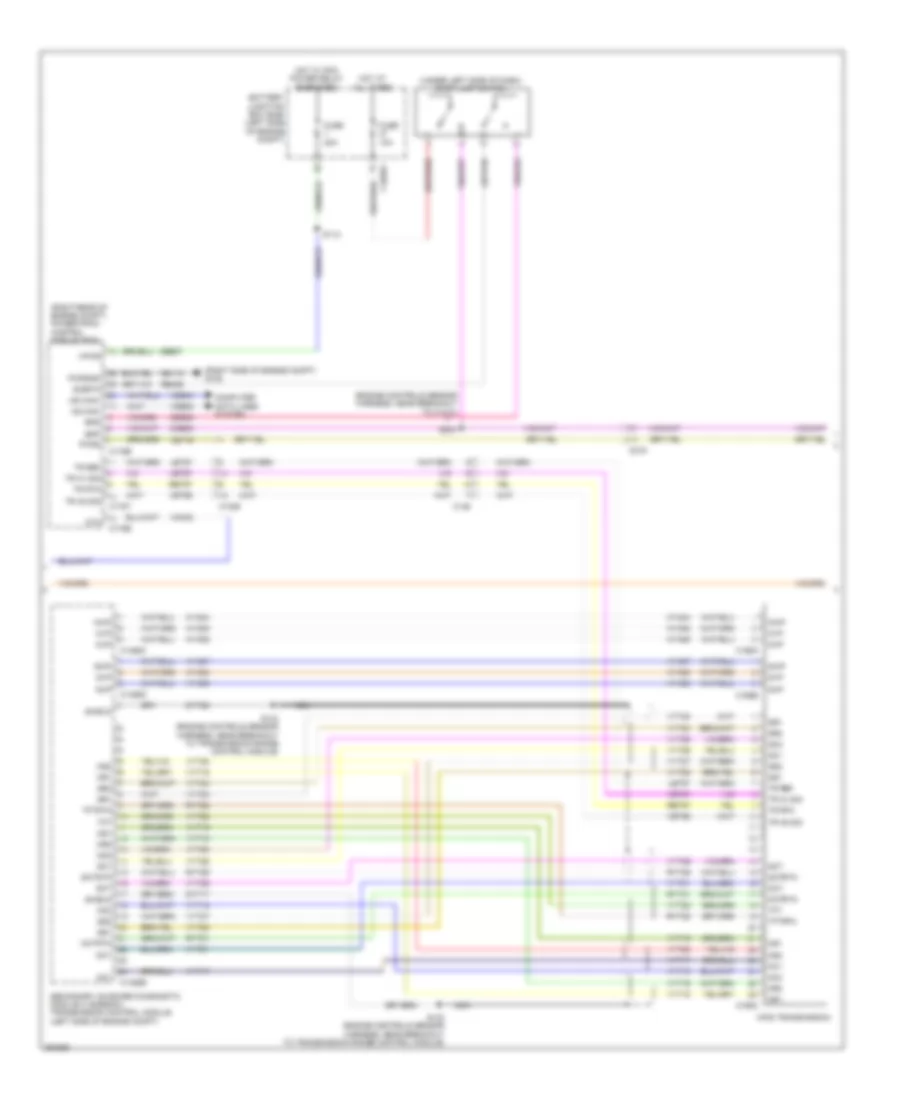
1.6L Turbo, A/T Wiring Diagram for Ford Fusion Titanium 2013

List of elements for 1.6L Turbo, A/T Wiring Diagram for Ford Fusion Titanium 2013:
- (engine controls sensor harness, near breakout to coil on plug 3)
- (instrument panel wiring harness, near breakout to g202)
- (left side of engine) electric motor coolant pump
- (not used)
- (under left side of dash) stop lamp switch
- 6f35 transmission (left side of transmission)
- Atfpc
- Atfpm
- Batt
- Battery junction box (bjb) (left side of engine compt)
- Body control module (left end of dash)
- Bpp
- Bps
- C1026
- C1035a
- C1035b
- C1232b
- C1232e
- C146
- C1520a
- C1520b
- C219
- C2280b
- C2280h
- Cbb07
- Ccb08
- Ces09
- Cet05
- Cet06
- Cet07
- Cet08
- Cet09
- Cet10
- Cet18
- Cet42
- Cet43
- Cet49
- Ch307
- Computer data lines system
- Cpc/fc2 hi spd
- Engine controls system
- Fuse 10a
- Fuse 15a
- Fuse 20a
- Fuse 5a
- G101 (left front of engine compt)
- G104 (right side of engine compt)
- Gd113
- Gnd
- Hot at all times
- Hot in on or start
- Hot w/ pcm power relay energized
- Hs can+
- Hs can-
- Le111
- Lpc
- Micro
- Nca
- Oss
- Oss/tr gnd
- Oss/tr vpwr
- Powertrain control module
- Pwr
- Pwr gnd
- Pwr/diag
- Re406
- Re454
- Ret24
- Run/start
- S112
- S139
- S140
- S142 (battery cable wiring harness, in breakout to transmission)
- S143
- S149 (engine control wiring harness, near breakout to knock sensor 2)
- S204
- S205 (main wiring harness, in breakout to steering column control module)
- S214
- S216
- Selector lever assembly (center console)
- Sig rtn
- Sigrtn
- Spd command
- Ssa
- Ssb
- Ssc
- Ssd
- Sse
- Sst rtn
- Sst+
- Sst-
- Tcc
- Tft
- Tft sig rtn
- Tr-p
- Transmission fluid pump (left side of engine compt)
- Trs
- Tspc
- Tss
- Tss/gnd
- Tss/oss/tr gnd
- Tss/oss/tr vpwr
- Tss/vpwr
- Vdb04
- Vdb05
- Vet26
- Vet27
- Vet32
- Vet33
- Vpwr
- Vyt11
- Vyt12
2.0L FLEX FUEL
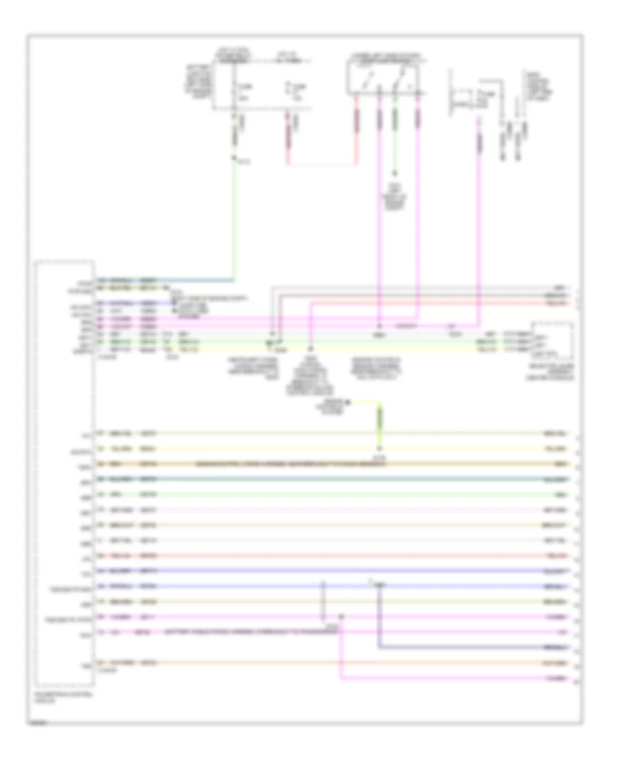
2.0L Flex Fuel, A/T Wiring Diagram (1 of 2) for Ford Fusion Titanium 2013
List of elements for 2.0L Flex Fuel, A/T Wiring Diagram (1 of 2) for Ford Fusion Titanium 2013:
- (engine controls sensor harness, near breakout to coil on plug 3)
- (instrument panel wiring harness, near breakout to g202)
- (not used)
- (under left side of dash) stop lamp switch
- Battery junction box (bjb) (left side of engine compt)
- Body control module (left end of dash)
- Bpp
- Bps
- C1035a
- C1381b
- C1381e
- C219
- C2280b
- C2280h
- Cbb07
- Ccb08
- Ces09
- Cet05
- Cet06
- Cet07
- Cet08
- Cet09
- Cet10
- Cet18
- Cet42
- Cet43
- Cet49
- Computer data lines system
- Engine controls system
- Fuse 10a
- Fuse 20a
- Fuse 5a
- G101 (left front of engine compt)
- G104 (right side of engine compt)
- Gd113
- Hot at all times
- Hot w/ pcm power relay energized
- Hs can+
- Hs can-
- Le111
- Lpc
- Micro
- Nca
- Oss
- Powertrain control module
- Pwr gnd
- Re406
- Re454
- Ret24
- S112
- S142 (battery cable wiring harness, in breakout to transmission)
- S143
- S149 (engine control wiring harness, near breakout to knock sensor 2)
- S204
- S205 (fusion) (main wiring harness, in breakout to steering column control module)
- S214
- S216
- Selector lever assembly (center console)
- Sig rtn
- Sigrtn
- Ssa
- Ssb
- Ssc
- Ssd
- Sse
- Sst rtn
- Sst+
- Sst-
- Tcc
- Tft
- Tr-p
- Tspc
- Tss
- Tss/oss/tr gnd
- Tss/oss/tr vpwr
- Vdb04
- Vdb05
- Vet26
- Vet27
- Vet32
- Vet33
- Vpwr
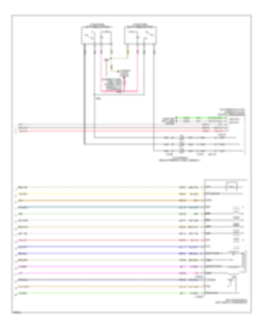
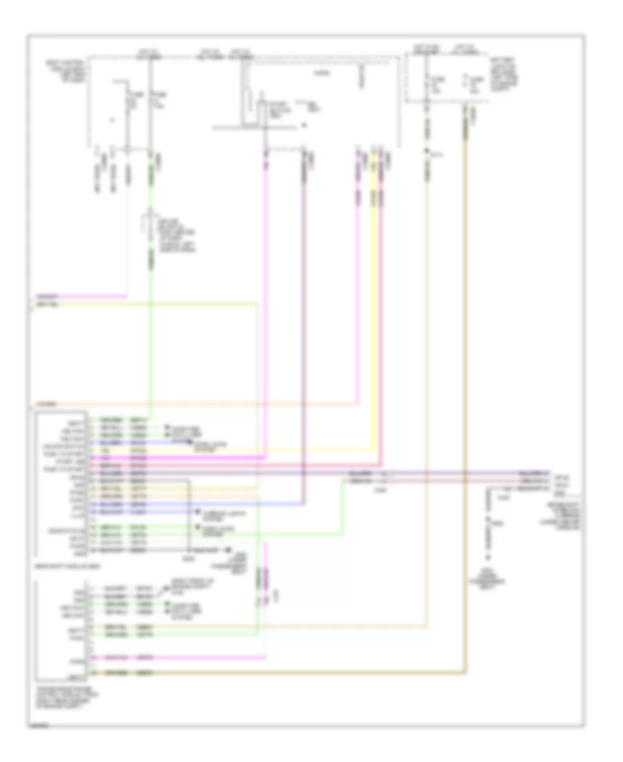
2.0L Flex Fuel, A/T Wiring Diagram (2 of 2) for Ford Fusion Titanium 2013
List of elements for 2.0L Flex Fuel, A/T Wiring Diagram (2 of 2) for Ford Fusion Titanium 2013:
- (if equipped) left paddle shifter
- (if equipped) right paddle shifter
- (on steering column) steering column control module (sccm)
- (steering wheel horn wiring harness, near breakout to clockspring) s296
- 6f35 transmission (left side of transmission)
- C1520a
- C1520b
- C218b
- C218c
- C2414a
- C2414d
- Cet05
- Cet06
- Cet07
- Cet08
- Cet09
- Cet10
- Cet18
- Cet42
- Cet43
- Cet49
- Clockspring (behind steering wheel assembly)
- Computer data lines system
- Hs2 can +
- Hs2 can -
- Interior lights system
- Le111
- Lpc
- Nca
- Oss
- Oss/tr gnd
- Oss/tr vpwr
- Pnk
- Re407
- Re454
- Ret24
- S293
- S294
- Ssa
- Ssb
- Ssc
- Ssd
- Sse
- Tcc
- Tft
- Tft sig rtn
- Tr-p
- Trs
- Tspc
- Tss
- Tss/gnd
- Tss/vpwr
- Vdb25
- Vdb26
- Vet26
- Vet27
- Vet32
- Vet33
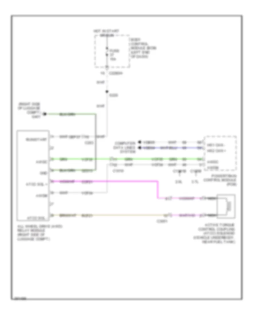
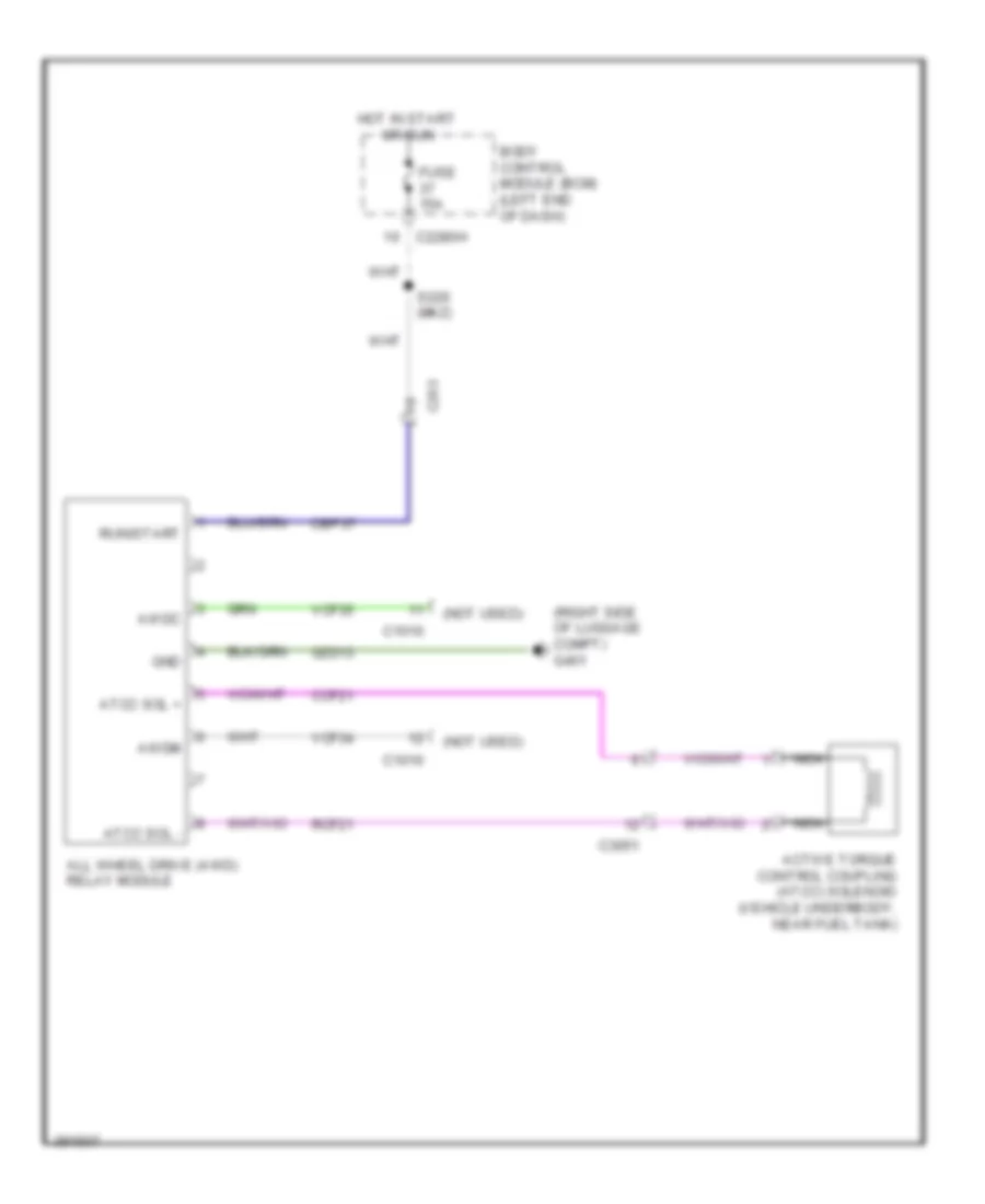
2.0L Flex Fuel, AWD Wiring Diagram for Ford Fusion Titanium 2013
List of elements for 2.0L Flex Fuel, AWD Wiring Diagram for Ford Fusion Titanium 2013:
- (right side of luggage compt) g401
- 2.0l
- 3.7l
- Active torque control coupling (atcc) solenoid (vehicle underbody, near fuel tank)
- All wheel drive (awd) relay module (right side of luggage compt)
- Atcc sol +
- Atcc sol -
- Awdc
- Awdm
- Body control module (bcm) (left end of dash)
- C1010
- C1381b
- C175b
- C2280h
- C263
- C3051
- Cbp37
- Ccf21
- Computer data lines system
- Fuse 15a
- Gd313
- Gnd
- Hot in start or run
- Hs1 can -
- Hs2 can +
- Nca
- Powertrain control module (pcm)
- Rcf21
- Run/start
- S220
- Vcf34
- Vcf35
- Vdb04
- Vdb05
2.0L HYBRID
2.0L Hybrid, A/T Wiring Diagram (1 of 3) for Ford Fusion Titanium 2013
List of elements for 2.0L Hybrid, A/T Wiring Diagram (1 of 3) for Ford Fusion Titanium 2013:
- (engine controls sensor harness, near breakout to abs module)
- (left front of engine compt) g100
- (left side of luggage compt) (hev) high voltage battery cooling fan
- (not used)
- (right front of engine compt) g101
- Battery junction box (left side of engine compt)
- C1026
- C1035a
- C1035b
- C145
- C1458a
- C1458e
- C146
- C210
- C215
- C219
- C340
- Cabin coolant heater (phev)
- Cbb51
- Ce318
- Ce436
- Ce613
- Chp01
- Computer data lines system
- Cto
- Cyt30
- Diag
- Engine controls system
- Ev switch
- Fuse 10a
- Fuse 15a
- Fuse 20a
- G101 (left front of engine compt)
- Gd120
- Gnd
- Hdc52
- Hdc53
- Hot at all times
- Hot in run or start
- Hot in start or run
- Hs can+
- Hs can-
- Hv+
- Hv-
- Mecsp
- Motor electronics coolant system pump (mecsp) (left front of engine compt)
- Pwm
- Pwrgnd
- S107
- S108 (phev)
- S119
- S141
- Sbb18
- Secondary on board diagnostic module c (sobdmc)/ transmission control module (left side of engine compt)
- Spd
- Tcm power relay
- Tcmrc
- Transmission fluid pump
- Vbatt
- Vdb04
- Vdb05
- Vmc02
- Vpwr
- Vyt11
- Vyt12
- Wake up
2.0L Hybrid, A/T Wiring Diagram (2 of 3) for Ford Fusion Titanium 2013
List of elements for 2.0L Hybrid, A/T Wiring Diagram (2 of 3) for Ford Fusion Titanium 2013:
- (engine controls sensor harness, near breakout to c1010)
- (right rear of engine compt) powertrain control module (pcm)
- (right side of engine compt) g105
- (under left side of dash) stop lamp switch
- Battery junction box (bjb) (left side of engine compt)
- Bpp
- Bps
- C1026
- C1035a
- C1458b
- C1458c
- C1458d
- C146
- C168a
- C168b
- C168c
- C175b
- C175e
- C175t
- C219
- Cbb07
- Ccb08
- Ces09
- Computer data lines system
- Cto
- Dyt17
- Dyt25
- Fuse 10a
- Fuse 20a
- Gc1
- Gc2
- Gct
- Gctrtn
- Gd113
- Gr1
- Gr2
- Gs1
- Gs2
- Gup
- Gvp
- Gwp
- Hf35 transmission
- Hot at all times
- Hot w/ pcm power relay energized
- Hs can+
- Hs can-
- Hya04
- Hya05
- Hya06
- Hya07
- Hya08
- Hya09
- Let57
- Mc1
- Mc2
- Mct
- Mctrtn
- Mr1
- Mr2
- Ms1
- Ms2
- Mup
- Mvp
- Mwp
- Nca
- Pwr2
- Pwrgnd
- Re406
- Ret57
- Ryt21
- Ryt22
- Ryt29
- S112
- S133 (engine controls sensor harness, near breakout to transmission range control module)
- S134 (engine controls sensor harness, near breakout to transmission range control module)
- S204
- Secondary on board diagnostic module c (sobdmc)/ transmission control module (left side of engine compt)
- Shield
- Sigrtn
- Tft
- Tftrtn
- Tr a1 sig
- Tr a2 sig
- Tr ref
- Tr rtn
- Vdb04
- Vdb05
- Vet56
- Vet57
- Vet76
- Vmc02
- Vpwr
- Vyt15
- Vyt16
- Vyt17
- Vyt18
- Vyt19
- Vyt20
- Vyt21
- Vyt22
- Vyt23
- Vyt24
- Vyt25
- Vyt26
- Vyt27
- Vyt28
- Vyt29
2.0L Hybrid, A/T Wiring Diagram (3 of 3) for Ford Fusion Titanium 2013
List of elements for 2.0L Hybrid, A/T Wiring Diagram (3 of 3) for Ford Fusion Titanium 2013:
- (not used)
- (right front of engine compt) g106
- Battery junction box (bjb) (left side of engine compt)
- Body control module (bcm) (left end of dash)
- Brake shift interlock override (under center console)
- Bsi (fet)
- Btsi
- C1035b
- C219
- C2280b
- C2280c
- C2280g
- C2280h
- C340
- Cbb23
- Ce436
- Cet53
- Cet82
- Cet83
- Computer data lines system
- Cpk34
- Cpk35
- Cpk36
- Cpl26
- Cpl30
- Door locks system
- Door status
- Fuse 15a
- Fuse 20a
- Fuse 5a
- Fuse 7.5a
- G303 (under passenger's seat)
- Gd123
- Gd383
- Gear shift module (gsm)
- Gnd
- Hot at all times
- Hot in on or start
- Hs2 can+
- Hs2 can-
- Illum
- Interior lights system
- Micro
- Or s1
- Or s2
- Push to start
- Pwr1
- Pwr2
- Pwr3
- S114
- S222
- Sbb76
- Sbp12
- Splice block 22 (mkz: center of dash) (fusion: left side of dash)
- Start button (fet)
- Start led
- Transmission range control module (trcm) (right rear corner of engine compt)
- Unlock switch
- Vbatt
- Vdb25
- Vdb26
- Vet76
- Vet77
- Vet78
- Vln04
- Wake up
2.0L Hybrid, AWD Wiring Diagram for Ford Fusion Titanium 2013
List of elements for 2.0L Hybrid, AWD Wiring Diagram for Ford Fusion Titanium 2013:
- (not used)
- (right side of luggage compt) g401
- Active torque control coupling (atcc) solenoid (vehicle underbody, near fuel tank)
- All wheel drive (awd) relay module
- Atcc sol +
- Atcc sol -
- Awdc
- Awdm
- Body control module (bcm) (left end of dash)
- C1010
- C2280h
- C263
- C3051
- Cbp37
- Ccf21
- Fuse 15a
- Gd313
- Gnd
- Hot in start or run
- Nca
- Rcf21
- Run/start
- S220 (mkz)
- Vcf34
- Vcf35
2.5L
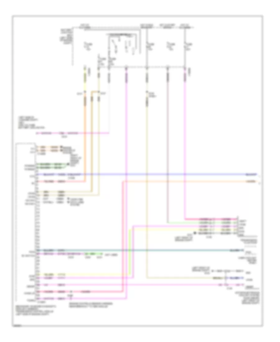
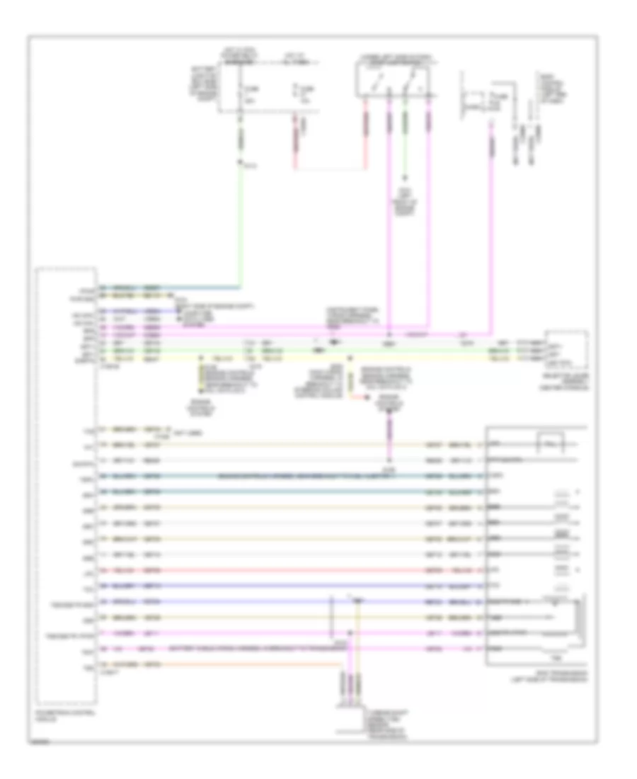
2.5L, A/T Wiring Diagram for Ford Fusion Titanium 2013
List of elements for 2.5L, A/T Wiring Diagram for Ford Fusion Titanium 2013:
- (engine controls sensor harness, near breakout to coil on plug 3)
- (instrument panel wiring harness, near breakout to g202)
- (not used)
- (not used) c1026
- (under left side of dash) stop lamp switch
- 6f35 transmission (left side of transmission)
- Battery junction box (bjb) (left side of engine compt)
- Body control module (left end of dash)
- Bpp
- Bps
- C1035a
- C1551b
- C1551t
- C219
- C2280b
- C2280h
- Cbb07
- Ccb08
- Ces09
- Cet05
- Cet06
- Cet07
- Cet08
- Cet09
- Cet10
- Cet18
- Cet25
- Cet34
- Cet42
- Cet43
- Computer data lines system
- Engine controls system
- Fuse 10a
- Fuse 20a
- Fuse 5a
- G101 (left front of engine compt)
- G104 (right side of engine compt)
- Gd113
- Harness, in breakout to steering column control module)
- Hot at all times
- Hot w/ pcm power relay energized
- Hs can+
- Hs can-
- Le111
- Lpc
- Micro
- Nca
- Oss
- Oss/tr gnd
- Oss/tr vpwr
- Powertrain control module
- Pwr gnd
- Re406
- Re407
- Ret24
- S112
- S141
- S142 (battery cable wiring harness, in breakout to transmission)
- S156 (engine controls harness, near breakout to fuel injector 1)
- S204
- S214
- S216
- Selector lever assembly (center console)
- Sig rtn
- Sigrtn
- Ssa
- Ssb
- Ssc
- Ssd
- Sse
- Sst rtn
- Sst+
- Sst-
- Tcc
- Tcs
- Tft
- Tft sig rtn
- Tr-p
- Trs
- Tspc
- Tss
- Tss/oss/tr gnd
- Tss/oss/tr vpwr
- Turbine shaft speed (tss) sensor (rear side of transmission)
- Vdb04
- Vdb05
- Vet26
- Vet27
- Vet32
- Vet33
- Vpwr