TRANSMISSION
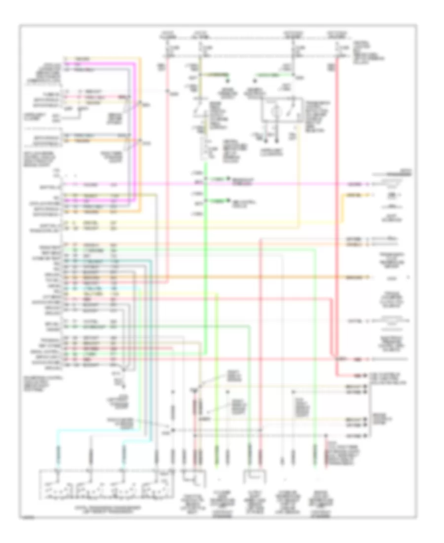
A/T Wiring Diagram for Ford Mustang 2001
List of elements for A/T Wiring Diagram for Ford Mustang 2001:
- (behind center of dash)
- (behind dash, right side of steering column)
- (right center of engine compt)
- (right rear of engine compt)
- (right side of engine)
- (top front of engine)
- 3.8l
- 4.6l
- 4r70w transmission
- Abs control module
- Anti-lock brake control module (right front of engine compt)
- Bpp sw input
- Brake pedal position switch (on brake pedal support)
- Brake pressure switch
- Brake shift interlock
- C220a
- C250
- Central junction box (behind dash, left of steering column)
- Cht sens
- Cylinder head temperature (cht) sensor (3.8l)
- Data link connector
- Data link power
- Digital transmission range sensor (left rear of transmission)
- Electronic pressure control (epc) solenoid
- Engine controls system
- Engine coolant temperature (ect) sensor (4.6l)
- Epc sol
- Fuel pump relay, fuel injectors, cooling fan relays
- Fuse 15a
- Fuse 20a
- Fuse 5a
- Fused b+
- G104 (left front of engine compt)
- Generic electronic module
- Ground
- Hot at all times
- Hot in run or start
- Ignition power
- Instrument cluster
- Instrument illumination
- Intake air temp
- Intake air temperature (iat) sensor (part of mass air (maf) sensor)
- Kapwr
- Oss sig
- Output shaft speed (oss) sensor (left side of trans)
- Powertrain control module (pcm) (behind right kick panel)
- Red
- Red red
- Ref votage
- S115
- S121 (right rear of engine compt)
- S126
- S129
- S134
- S135
- S207
- S234
- S252
- S253
- S259
- S262
- S272
- S275
- Scp data bus +
- Scp data bus -
- Shift sol a
- Shift sol b
- Shift solenoids
- Signal control
- Ssa
- Ssb
- Tcc sol
- Temp sens
- Throttle position (tp) sensor (on throttle body)
- Torque converter clutch (tcc) solenoid
- Tps signal
- Tr1
- Tr2
- Tr3
- Tr4
- Trans cntrl sw
- Trans temp
- Transmission control switch (tcs) (on center console, right of gear selector)
- Transmission fluid temperature sensor
 English