TRANSMISSION
2.0L
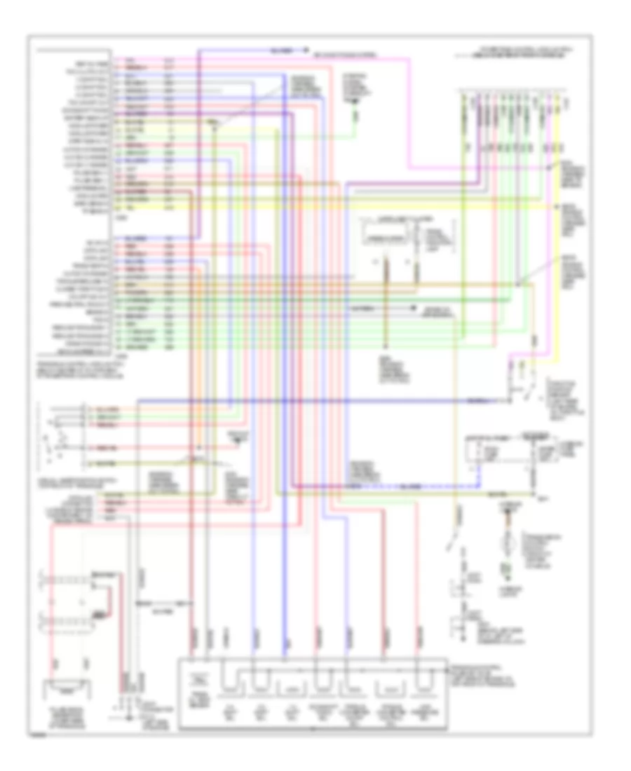
2.0L, Transmission Wiring Diagram for Ford Probe GT 1995

List of elements for 2.0L, Transmission Wiring Diagram for Ford Probe GT 1995:
- (behind left side of i/p, left of steering column)
- (below center front of center console)
- (emission harness, near safety wall grommet)
- (emission harness, near left engine mount)
- (engine compartment, left fender apron)
- (on left fender apron) g104
- (partial)
- (top of transaxle)
- 3-2 timing/ coast clutch sol sol sol sol
- A/c high press. cut out switch
- A/c on/off
- Boo
- Brake on/off switch
- C215
- Cd4e transaxle
- Coast cltch
- Data link
- Data link connector (left side of engine compt, on fender apron)
- Ect temp
- Elect pressure control sol
- Engine compartment fuse block (left side of engine compt, above wheelwell)
- Engine compt fuse box
- Engine coolant temperature sensor (top left side of engine)
- Engine fuse 15a
- Epc sol
- F/p inj fuse 30a
- G102
- G204
- Gnd
- Hot at all times
- Hot in start or run
- Iat in
- Instrument cluster
- Intake air temperature sensor (on left side of air cleaner assembly)
- Interior fuse panel
- Interior lights
- Joint connector c203 (behind left side of i/p)
- Joint connector c234 (behind left side of i/p)
- Joint connector c264 (below center front of console, near pcm)
- Kapwr
- Maf
- Malfunction indicator lamp (mil)
- Mass air flow sensor sensor (top left rear of engine compt, rear of cleaner assembly)
- Meter fuse 15a
- Mil ind
- Mlps in
- Pcm power relay
- Powertrain control module (pcm)
- Red
- Room fuse 15a
- S102
- S118
- S138 (engine harness, near ho2s)
- S163
- S179 (front of engine compartment)
- S2003
- S215
- S239
- S287 (emission harness, near break out to pcm)
- Shift sol #1
- Shift sol #2
- Shift sol 1
- Shift sol 2
- Sig rtn
- Tccs
- Tcil
- Tcs in
- Throttle position sensor (top left rear of engine, on throttle body)
- Torque converter converter converter converter clutch clutch clutch clutch sol sol sol sol
- Tot in
- Tp in
- Trans oil temp sensor
- Trans. control indicator lamp
- Transmission control switch (front of center console)
- Transmission range sensor (top front of transaxle)
- Tsss in
- Turbine shaft speed sensor (on left side of transaxle)
- V ref
- Vehicle speed sensor (lower rear of transaxle)
- Vpwr
- Vss (+)
- Vss (-)
2.5L
2.5L, Transmission Wiring Diagram for Ford Probe GT 1995
List of elements for 2.5L, Transmission Wiring Diagram for Ford Probe GT 1995:
- (behind left side of i/p, left of steering column)
- (below center of front console)
- (emission harness, near break out to pcm)
- (emission harness, near break out to pcm) s239
- (emission harness, near break out to tcm)
- (engine control harness, near pcm)
- (left rear of engine, on throttle body)
- (lh side of engine compartment, on fender apron)
- (starter interrupt
- 1-2 shift sol
- 2-3 shift sol
- 3-4 shift sol
- A/c on in
- Air conditioning system
- Back-up lights
- Baro sens in
- Battery back-up
- Brake in
- Brake on/ off switch
- C246
- C247
- C248
- C258
- C259
- Closed throttle in
- Crank pos sig in
- Data link
- Data link connector
- Downshift timing
- Downshift timing sol
- G112 (left side of engine)
- G204
- Hot at all times
- Hot in run or start
- Instrument cluster
- Interior fuse panel
- Interior lights
- Joint conn.
- Joint connector
- Line press sol
- Line pressure sol
- Manual lever position switch (top front of transaxle)
- Meter fuse 15a
- Mlp sw (1 range)
- Mlp sw (2 range)
- Mlp sw (d range)
- Mlp sw (r range)
- Module grd
- Module power
- O/d off ind out
- Park/neutral pos out
- Powertrain control module (pcm)
- Pulse gen (+)
- Pulse gen (-)
- Pulse signal generator (lower rear of transaxle)
- Red
- Reduce torque sig 1
- Reduce torque sig 2
- Ref voltage
- Relay)
- Room fuse 15a
- S123
- S150 (emission harness, near take out to pcm)
- S193 (emission harness, near tr sensor)
- S2008 (engine control harness, near pcm)
- S2009
- S211
- S240
- S241
- S279
- S296 (emission harness, near break out to pcm)
- Speedometer
- Start signal in
- Starting system
- Tcc clutch out
- Tcc on/off out
- Tcs in
- Throttle position sensor
- Torque converter control sol
- Torque converter on/off sol
- Torque reduced in
- Tp sens in
- Trans oil temp sensor
- Trans temp in
- Trans. control indicator lamp
- Transaxle control module (tcm) (below center of i/p, forward of powertrain control module)
- Transaxle control solenoid valve (left side of engine, on top front of transaxle)
- Transmission control switch (front of center console)
- Vehicle speed in (+)