TRANSMISSION
4WD Wiring Diagram for Ford Ranger 2005

List of elements for 4WD Wiring Diagram for Ford Ranger 2005:
- (at left front of vehicle floor) g205
- (in dash to headlight junction harness, near breakout for g102)
- (in engine control sensor & fuel charge harness, at breakout for powertrain control module) g106 (at top rear of engine compt)
- (in main harness, near breakout for smart junction box) s236
- (in main harness, near breakout for instrument cluster) s213
- (in main harness, near breakout for power point)
- (in main harness, near breakout for steering column air bag sliding contact)
- (left side of transmission) digital transmission range (dtr) sensor
- 2.3l
- 4wd hi
- 4wd hi ind
- 4wd lo
- 4wd lo ind
- 4wd switch
- A/t
- Battery junction box (bjb) (at left rear side of engine compt)
- Bpp switch
- Brake pedal position switch (behind left side of dash, on brake pedal support)
- C220a
- C2280a
- C2280b
- C2280c
- C281a
- C281b
- Clutch pedal position switch (behind left side of dash, top of brake pedal support)
- Computer data lines system
- Cruise control system
- Data link connector (dlc) (at bottom of steering column)
- Except 2.3l
- Four-wheel drive control module (behind left center of dash)
- Four-wheel drive switch
- Fuse 10a
- Fuse 15a
- Fuse 20a
- Fuse 5a
- G204 (under front of center console)
- G205 (at left front of vehicle floor)
- Gearmotor encoder assembly (on transfer case)
- Ground
- Head
- Hot at all times
- Hot in run
- Hot in run or start
- Hot in start
- Ign (run)
- Ign (st/run)
- Illum
- Instrument cluster
- Instrument cluster system
- Interior lights system
- Interior lights system (dimmer)
- Iso bus
- M/t
- Main light switch
- Micro- processor
- Motor 1
- Motor 2
- Motor 3
- Motor 4
- Motor 5
- Neutral sens
- Off
- Park
- Pnk
- Powertrain control module (pcm) (right rear of engine compt, through firewall)
- S116
- S145
- S200 (in main harness, near breakout for center of dash)
- S203
- S208 (in main harness, near breakout for audio unit)
- S209
- S216
- S223 (in main harness, near breakout for left side of dash)
- S227
- S258 (in main harness, near breakout for smart junction box)
- Sig return
- Smart junction box (sjb) (behind right side of dash)
- Starter relay
- Tan/ red
- Tan/red
- Transfer case
- Vss input
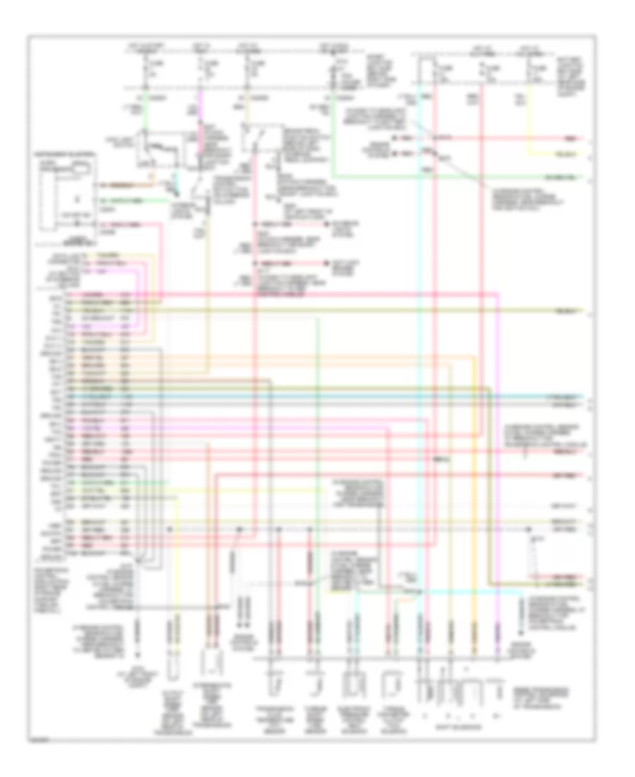
2.3L
2.3L, A/T Wiring Diagram (1 of 2) for Ford Ranger 2005
List of elements for 2.3L, A/T Wiring Diagram (1 of 2) for Ford Ranger 2005:
- (dlc) (at bottom of steering column)
- (in dash to headlight junction harness, at breakout to battery junction box)
- (in engine control sensor & fuel charge harness, at breakout for powertrain control module)
- (in engine control sensor & fuel charge harness, near breakout for fuel injector 4)
- (in engine control sensor & fuel charge harness, near breakout for transmission)
- (in engine control sensor & fuel charge harness, near breakout to swirl control solenoid valve)
- 5r44e transmission control solenoids (at left side of transmission)
- Anti-lock brakes system
- Battery junction box (bjb) (at left rear side of engine compt)
- Bpp
- Brake pedal position switch (behind left side of dash, on brake pedal support)
- C220a
- C220b
- C2280a
- C2280b
- C2280c
- Check engine ind
- Cht
- Data link connector
- Dlc
- Dlc (+)
- Dlc (-)
- Electronic pressure control (epc) solenoid
- Engine controls system
- Epc
- Exterior lights system
- Fuse 10a
- Fuse 15a
- Fuse 30a
- Fuse 5a
- G104 (at left front of engine compt)
- G205 (at left front of vehicle floor)
- Ground
- Harness, near breakout for smart junction box) nca
- Head
- Hot at all times
- Hot in run
- Hot in run or start
- Hot in start or run
- Instrument cluster
- Interior lights system
- Intermediate shaft speed (iss) sensor (on left side of transmission)
- Iss
- Junction box)
- Junction harness, near breakout to abs control module)
- Main light switch
- Micro-
- Mil
- Nca
- O/d off ind
- Off
- Oss
- Output shaft speed (oss) sensor (on left rear of transmission)
- Park
- Pcm power diode
- Power
- Powertrain control module (pcm) (right rear of engine compt, through firewall)
- Prndl
- Processor
- Ptc 1a
- Red
- S107
- S113
- S143
- S148
- S149
- S150
- S153
- S154
- S236 (in main harness, near breakout for smart junction box)
- Shift solenoids
- Sig rtn
- Smart junction box (sjb) (behind right side of dash)
- Ss a
- Ss b
- Ss c
- Ss d
- Tcc
- Tcil
- Tcs
- Tft
- Torque converter clutch (tcc) solenoid
- Tr1
- Tr2
- Tr3a
- Tr4
- Transmission control switch (tcs) (on steering column)
- Transmission fluid temperature (tft) sensor
- Tss
- Turbine shaft speed (tss) sensor
- Vbatt
- Vref
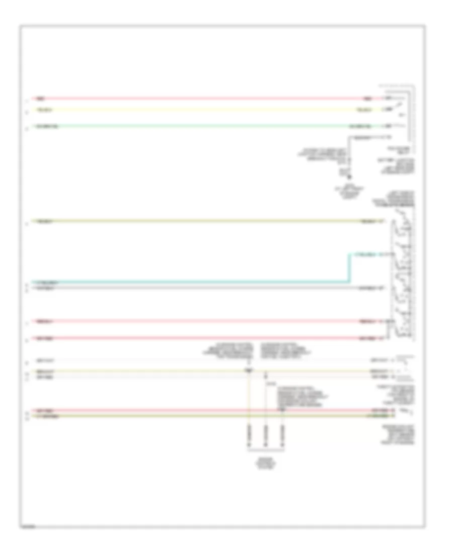
2.3L, A/T Wiring Diagram (2 of 2) for Ford Ranger 2005
List of elements for 2.3L, A/T Wiring Diagram (2 of 2) for Ford Ranger 2005:
- (in dash to headlight junction harness, near breakout for g102) s118
- (in engine control sensor & fuel charge harness, near breakout for idle air valve)
- (in engine control sensor & fuel charge harness, near breakout for swirl control monitor)
- (left side of transmission) digital transmission range (dtr) sensor
- Battery junction box (bjb) (left rear side of engine compt)
- Cylinder head temperature (cht) sensor (on right side of cylinder head)
- Engine controls system
- G104 (at left front of engine compt)
- Pcm power relay
- R p
- Red
- S137
- S151
- S152 (in engine control sensor & fuel charge harness, near breakout for transmission)
- Throttle position (tp) sensor (top right side of engine, on throttle body)
3.0L
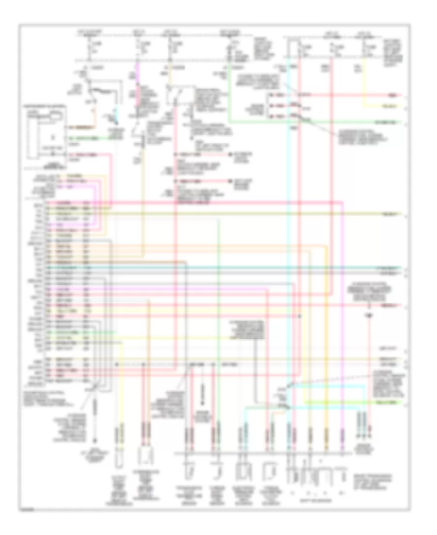
3.0L, A/T Wiring Diagram (1 of 2) for Ford Ranger 2005
List of elements for 3.0L, A/T Wiring Diagram (1 of 2) for Ford Ranger 2005:
- (dlc) (bottom of steering column)
- (in dash to headlight junction harness, at breakout to battery junction box)
- (in engine control sensor & fuel charge harness, at breakout for powertrain control module)
- (in engine control sensor & fuel charge harness, near breakout for heated oxygen sensor 21)
- (in engine control sensor & fuel charge harness, near breakout for transmission)
- (in engine control sensor & fuel charge harness, near breakout to fuel injector 3)
- (main harness, near breakout for smart junction box)
- 5r44e transmission control solenoids (at left side of transmission)
- Anti-lock brakes system
- Battery junction box (bjb) (at left rear side of engine compt)
- Bpp
- Brake pedal position switch (behind left side of dash, on brake pedal support)
- C220a
- C220b
- C2280a
- C2280b
- C2280c
- Check engine ind
- Data link connector
- Dlc
- Dlc (+)
- Dlc (-)
- Ect
- Electronic pressure control (epc) solenoid
- Engine controls system
- Epc
- Exterior lights system
- Fuse 10a
- Fuse 15a
- Fuse 30a
- Fuse 5a
- G104 (at left front of engine compt)
- G205 (at left front of vehicle floor)
- Ground
- Head
- Hot at all times
- Hot in run
- Hot in run or start
- Hot in start or run
- Instrument cluster
- Interior lights system
- Intermediate shaft speed (iss) sensor (on left side of transmission)
- Iss
- Junction box)
- Junction harness, near breakout to abs control module)
- Main light switch
- Micro-
- Mil
- Nca
- O/d off ind
- Off
- Oss
- Output shaft speed (oss) sensor (on left rear of transmission)
- Park
- Pcm power diode
- Power
- Powertrain control module (pcm) (right rear of engine compt, through firewall)
- Prndl
- Processor
- Ptc 1a
- Red
- S100
- S104
- S106
- S107
- S113
- S129 (in engine control sensor & fuel charge harness, at breakout for powertrain control module)
- S143
- S236
- S237 (in main harness, near breakout for smart junction box)
- Shift solenoids
- Sig rtn
- Smart junction box (sjb) (behind right side of dash)
- Ss a
- Ss b
- Ss c
- Ss d
- Tcc
- Tcil
- Tcs
- Tft
- Torque converter clutch (tcc) solenoid
- Tr1
- Tr2
- Tr3a
- Tr4
- Transmission control switch (tcs) (on steering column)
- Transmission fluid temperature (tft) sensor
- Tss
- Turbine shaft speed (tss) sensor
- Vbatt
- Vref
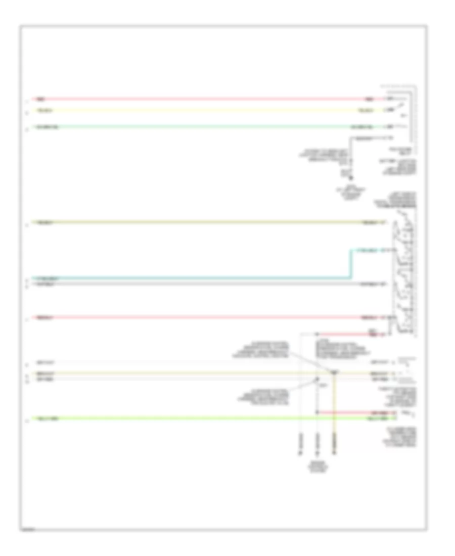
3.0L, A/T Wiring Diagram (2 of 2) for Ford Ranger 2005
List of elements for 3.0L, A/T Wiring Diagram (2 of 2) for Ford Ranger 2005:
- (in dash to headlight junction harness, near breakout for g102) s118
- (in engine control sensor & fuel charge harness, near breakout for fuel injector 5)
- (in engine control sensor & fuel charge harness, near breakout for fuel injector 6)
- (left side of transmission) digital transmission range (dtr) sensor
- Battery junction box (bjb) (at left rear side of engine compt)
- Engine controls system
- Engine coolant temperature (ect) sensor (on top front of engine)
- G104 (at left front of engine compt)
- Pcm power relay
- R p
- Red
- S137
- S139
- Throttle position (tp) sensor (top left front of engine, on throttle body)
4.0L
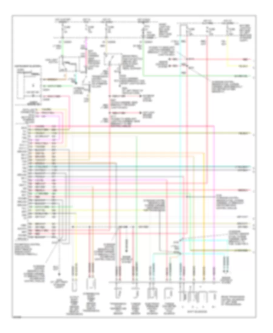
4.0L, A/T Wiring Diagram (1 of 2) for Ford Ranger 2005
List of elements for 4.0L, A/T Wiring Diagram (1 of 2) for Ford Ranger 2005:
- (dlc) (at bottom of steering column)
- (in dash to headlight junction harness, at breakout to battery junction box)
- (in engine control sensor & fuel charge harness, at breakout for powertrain control module)
- (in engine control sensor & fuel charge harness, near breakout for ignition coil)
- (in engine control sensor & fuel charge harness, near breakout for transmission)
- (in engine control sensor & fuel charge harness, near breakout to heated oxygen sensor 11)
- (in engine control sensor & fuel charge harness, near breakout to heated oxygen sensor 12)
- 5r55e transmission control solenoids (at left side of transmission)
- Anti-lock brakes system
- Battery junction box (bjb) (at left rear side of engine compt)
- Bpp
- Brake pedal position switch (behind left side of dash, on brake pedal support)
- C220a
- C220b
- C2280a
- C2280b
- C2280c
- Check engine ind
- Data link connector
- Dlc
- Dlc (+)
- Dlc (-)
- Ect
- Electronic pressure control (epc) solenoid
- Engine controls system
- Epc
- Exterior lights system
- Fuse 10a
- Fuse 15a
- Fuse 30a
- Fuse 5a
- G104 (at left front of engine compt)
- G205 (at left front of vehicle floor)
- Ground
- Harness, near breakout for smart junction box) nca
- Head
- Hot at all times
- Hot in run
- Hot in run or start
- Hot in start or run
- Instrument cluster
- Interior lights system
- Intermediate shaft speed (iss) sensor (on left rear of transmission)
- Iss
- Junction box)
- Junction harness, near breakout to abs control module)
- Main light switch
- Micro-
- Mil
- Nca
- O/d off ind
- Off
- Oss
- Output shaft speed (oss) sensor (on left rear of transmission)
- Park
- Pcm power diode
- Power
- Powertrain control module (pcm) (right rear of engine compart through firewall)
- Prndl
- Processor
- Ptc 1a
- Red
- S104
- S107 (in engine control sensor & fuel charge harness, at breakout for powertrain control module)
- S113
- S129
- S140
- S141
- S143
- S144
- Shift solenoids
- Sig rtn
- Smart junction box (sjb) (behind right side of dash)
- Ss a
- Ss b
- Ss c
- Ss d
- Tcc
- Tcil
- Tcs
- Tft
- Torque converter clutch (tcc) solenoid
- Tr1
- Tr2
- Tr3a
- Tr4
- Transmission control switch (tcs) (on steering column)
- Transmission fluid temperature (tft) sensor
- Tss
- Turbine shaft speed (tss) sensor
- Vbatt
- Vref
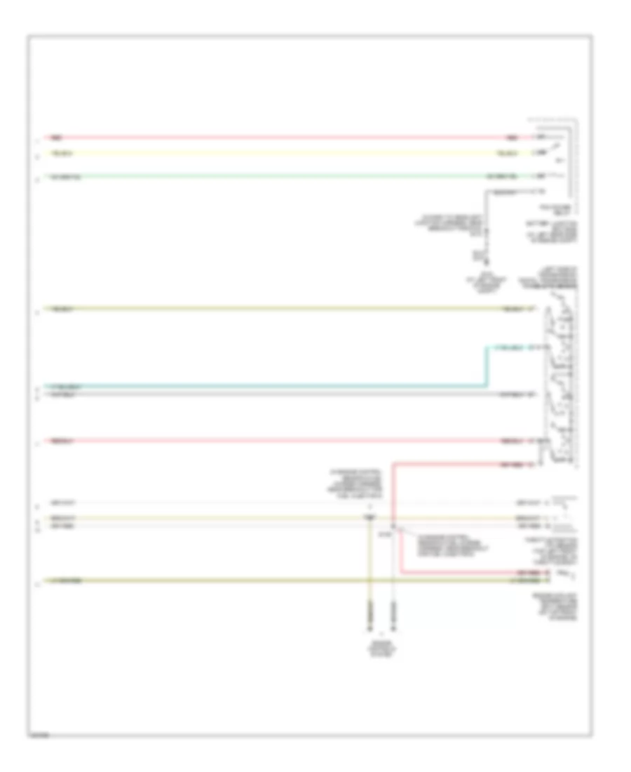
4.0L, A/T Wiring Diagram (2 of 2) for Ford Ranger 2005
List of elements for 4.0L, A/T Wiring Diagram (2 of 2) for Ford Ranger 2005:
- (in dash to headlight junction harness, near breakout for g102) s118
- (in engine control sensor & fuel charge harness, near breakout for engine coolant temperature sender) s133
- (in engine control sensor & fuel charge harness, near breakout for fuel injector 4)
- (in engine control sensor & fuel charge harness, near breakout for transmission)
- (left side of transmission) digital transmission range (dtr) sensor
- Battery junction box (bjb) (left rear side of engine compt)
- Engine controls system
- Engine coolant temperature (ect) sensor (on top right front of engine)
- G104 (at left front of engine compt)
- Pcm power relay
- R p
- Red
- S135
- S137
- Throttle position (tp) sensor (top front of engine, on throttle body)