TRANSMISSION
4WD Wiring Diagram for Ford Ranger 2007

List of elements for 4WD Wiring Diagram for Ford Ranger 2007:
- (in main harness, near breakout to blend door actuator) s228
- (in main harness, near breakout to clockspring)
- (in main harness, near breakout to deactivator switch) s203
- (under front of center console) g204
- (w/ 4x4)
- 4wd hi
- 4wd lo
- 4wd sw rtn
- 4wd sw sig
- Battery junction box (bjb) (left rear side of engine compt)
- Breakout to instrument cluster)
- C220a
- C220b
- C2280b
- C2280c
- C281a
- C281b
- Can+
- Can-
- Cbp10
- Ccb15
- Ccf07
- Ccf08
- Ccf13
- Ccf14
- Ccf15
- Ccf16
- Ccf17
- Ccf20
- Ccf21
- Computer data lines system
- Cpl12
- Digital transmission range (dtr) sensor (a/t) (left side of transmission)
- Door ajar
- Exterior
- Four-wheel drive control module (behind left center of dash)
- Four-wheel drive switch
- Fuse 10a
- Fuse 15a
- Fuse 20a
- Fuse 5a
- G107 (right rear of engine compt)
- G301 (under driver's seat)
- Gd161
- Gd174
- Gearmotor encoder assembly (on transfer case)
- Gnd
- Hot at all times
- Hot in run or start
- Illum
- Instrument cluster
- Interior lights system
- Lights system
- Low current board
- Micro- processor
- Mtr ccw
- Mtr cw
- Neu tow ind
- Neutral tow indicator (w/ 4x4)
- Off
- Pos rtn
- Pos2 mtr
- Pos3 mtr
- Pos4 mtr
- Pos5 mtr
- Rcf09
- Rcf13
- Red
- S100 (near breakout to powertrain control module)
- S203 (in main harness, near breakout to deactivator switch)
- S212 (in main harness, near red
- S214
- S223 (in main harness, near breakout to front cigar lighter)
- Sbb27
- Sbb28
- Sense
- Smart junction box (sjb) (right kick panel)
- Trans neu
- Vbatt
- Vdb04
- Vdb05
- Vpwr
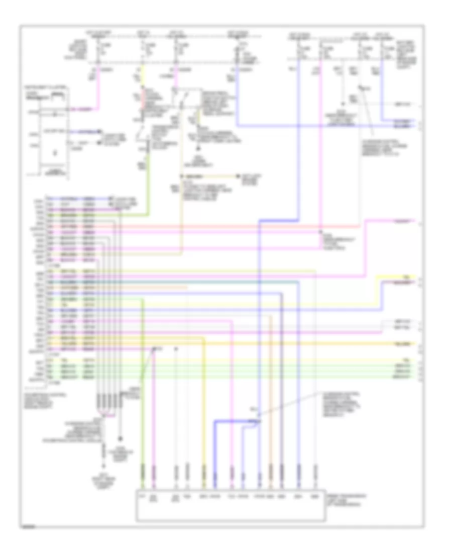
2.3L
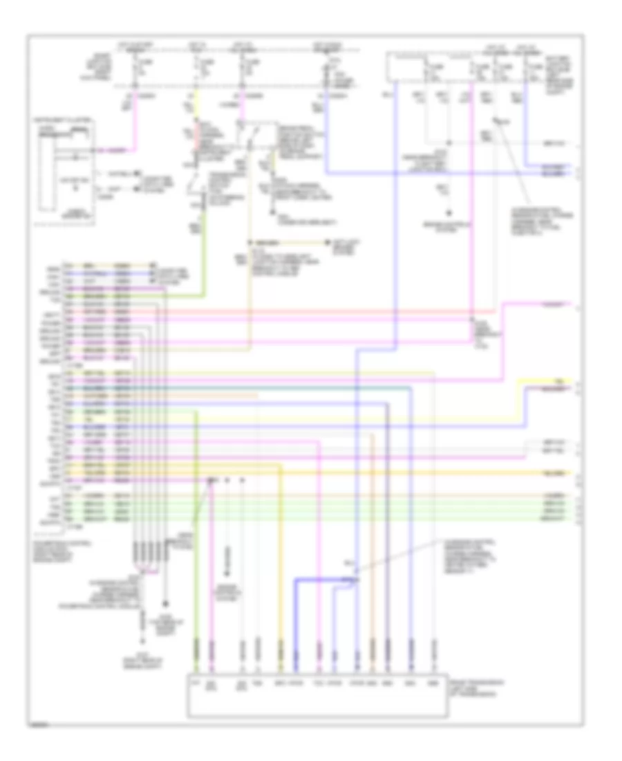
2.3L, A/T Wiring Diagram (1 of 2) for Ford Ranger 2007
List of elements for 2.3L, A/T Wiring Diagram (1 of 2) for Ford Ranger 2007:
- (in engine control sensor & fuel charge harness, near breakout to fuel injector 4)
- (in engine control sensor & fuel charge harness, near breakout to heated oxygen sensor 11)
- (near breakout to g106)
- 5r44e transmission (left side of transmission)
- Anti-lock brakes system
- Battery junction box (bjb) (left rear side of engine compt)
- Bpp
- Brake pedal position switch (behind left side of dash, on brake pedal support)
- C175b
- C175e
- C175t
- C220b
- C2280a
- C2280b
- C2280c
- Can+
- Can-
- Cbb39
- Ccb15
- Cdb08
- Ce116
- Cet05
- Cet06
- Cet07
- Cet18
- Cet19
- Cet34
- Cet44
- Check engine ind
- Cht
- Computer data lines system
- Engine controls system
- Epc
- Feps
- Fuse 10a
- Fuse 15a
- Fuse 30a
- Fuse 5a
- G106 (top rear of engine compt)
- G107 (right rear of engine compt)
- G301 (under driver's seat)
- Gd108
- Ground
- Harness, near breakout to instrument cluster)
- Hot at all times
- Hot in run
- Hot in run or start
- Hot in start or run
- Instrument cluster
- Iss
- Junction harness, near breakout to abs control module)
- Le423
- Micro-
- Nca
- O/d off ind
- Oss
- Pcm power diode
- Power
- Powertrain control module (pcm) (right rear of engine compt)
- Prndl
- Processor
- Ptc 1a
- Re405
- Re406
- Ret04
- S100 (in engine control sensor & fuel charge harness, near breakout to powertrain control module)
- S102
- S105
- S109 (near breakout to c133)
- S112
- S123 (near breakout to battery junction box)
- S220 (in main harness, near breakout to front cigar lighter)
- Sbb21
- Sig rtn
- Smart junction box (sjb) (right kick panel)
- Ss a
- Ss b
- Ss c
- Ss d
- Ssa
- Ssb
- Ssc
- Ssd
- Tcc
- Tcs
- Tft
- Tps
- Tr1
- Tr2
- Tr3a
- Tr4
- Transmission control switch (tcs) (on steering column)
- Tss
- Vbatt
- Vdb04
- Vdb05
- Ve739
- Ve819
- Vet27
- Vet28
- Vet29
- Vet30
- Vet31
- Vet33
- Vpwr
- Vref
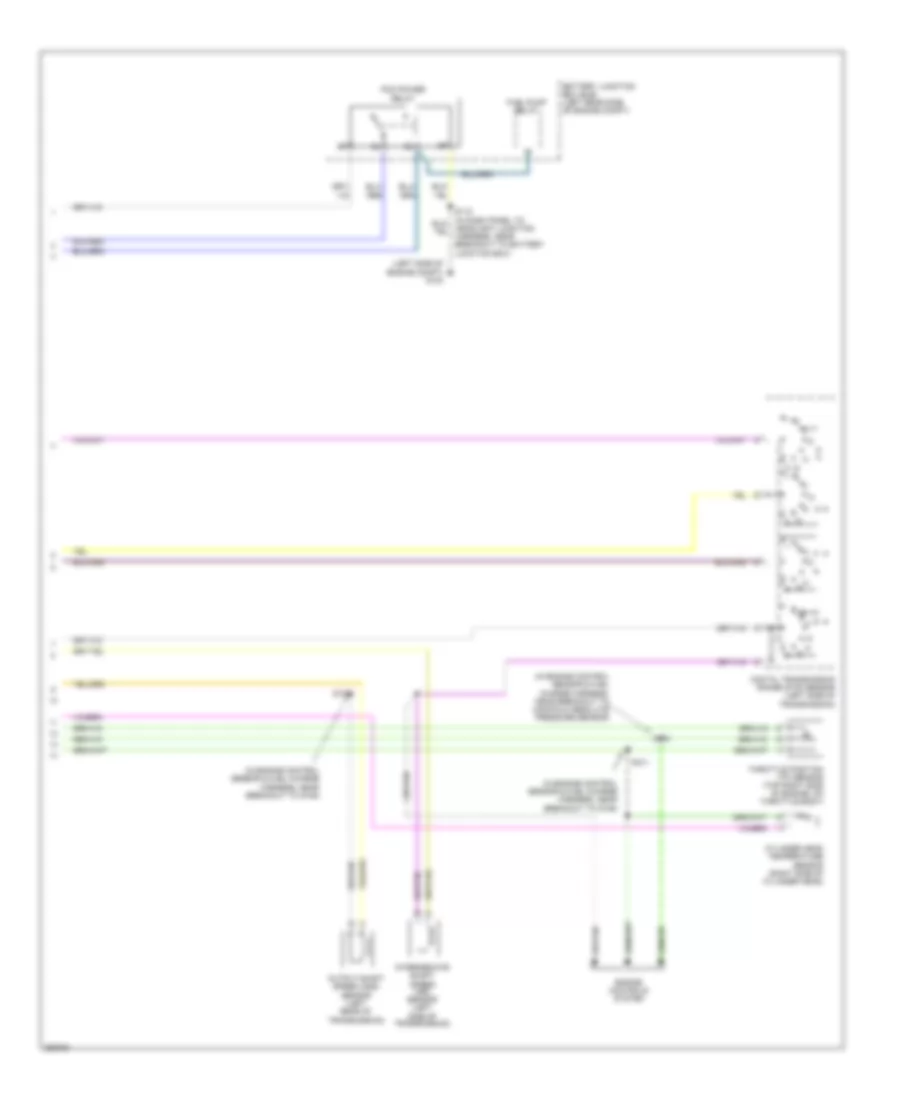
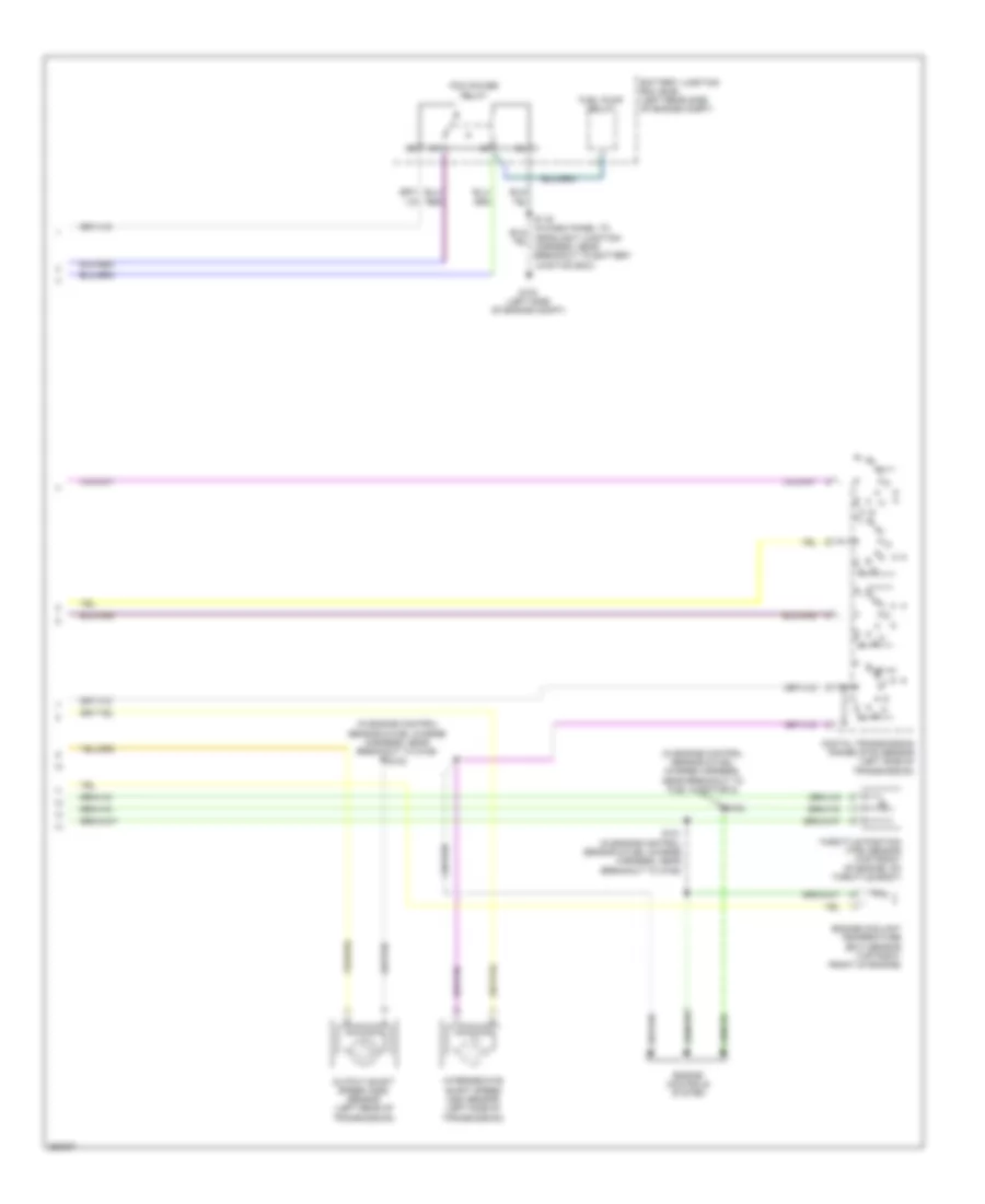
2.3L, A/T Wiring Diagram (2 of 2) for Ford Ranger 2007
List of elements for 2.3L, A/T Wiring Diagram (2 of 2) for Ford Ranger 2007:
- (in engine control sensor & fuel charge harness, near breakout to g106)
- (in engine control sensor & fuel charge harness, near breakout to manifold absolute pressure sensor)
- (left side of engine compt) g103
- Battery junction box (bjb) (left rear side of engine compt)
- Cylinder head temperature sensor (right side of cylinder head)
- Digital transmission range (dtr) sensor (left side of transmission)
- Engine controls system
- Fuel pump relay
- Intermediate shaft speed (iss) sensor (left side of transmission)
- N r
- Output shaft speed (oss) sensor (left rear of transmission)
- Pcm power relay
- S101
- S102
- S103
- Throttle position (tp) sensor (top right side of engine, on throttle body)
3.0L
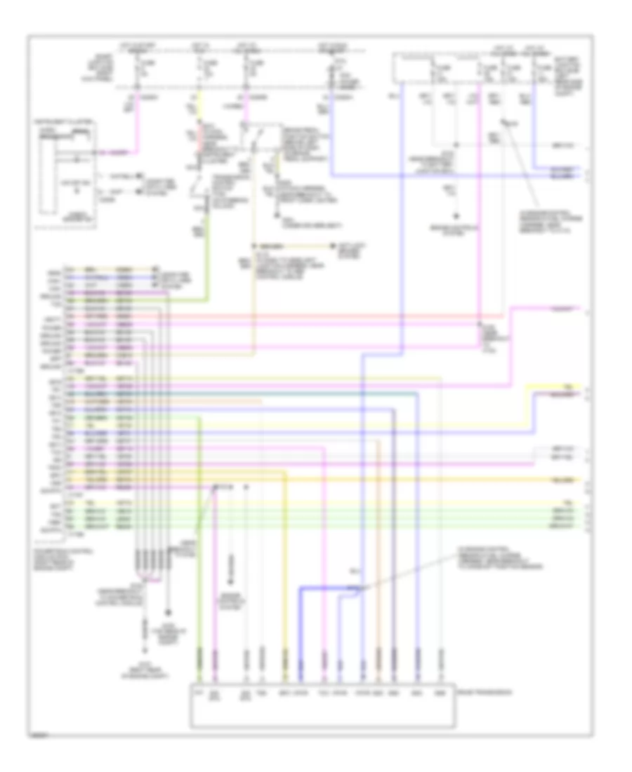
3.0L, A/T Wiring Diagram (1 of 2) for Ford Ranger 2007
List of elements for 3.0L, A/T Wiring Diagram (1 of 2) for Ford Ranger 2007:
- (in engine control sensor & fuel charge harness, near breakout to c110)
- (in engine control sensor & fuel charge harness, near breakout to camshaft position sensor)
- (near breakout to g106)
- 5r44e transmission
- Anti-lock brakes system
- Battery junction box (bjb) (left rear side of engine compt)
- Bpp
- Brake pedal position switch (behind left side of dash, on brake pedal support)
- C175b
- C175e
- C175t
- C220b
- C2280a
- C2280b
- C2280c
- Can+
- Can-
- Cbb39
- Ccb15
- Cdb08
- Cet05
- Cet06
- Cet07
- Cet18
- Cet19
- Cet34
- Cet44
- Check engine ind
- Computer data lines system
- Ect
- Engine controls system
- Epc
- Feps
- Fuse 10a
- Fuse 15a
- Fuse 30a
- Fuse 5a
- G106 (top rear of engine compt)
- G107 (right rear of engine compt)
- G301 (under driver's seat)
- Gd108
- Ground
- Harness, near breakout to instrument cluster)
- Hot at all times
- Hot in run
- Hot in run or start
- Hot in start or run
- Instrument cluster
- Iss
- Junction harness, near breakout to abs control module)
- Le423
- Micro-
- Nca
- O/d off ind
- Oss
- Pcm power diode
- Power
- Powertrain control module (pcm) (right rear of engine compt)
- Prndl
- Processor
- Ptc 1a
- Re405
- Re406
- Ret04
- S100 (near breakout to powertrain control module)
- S102
- S105
- S109 (near breakout to c133)
- S112
- S123 (near breakout to battery junction box)
- S220 (in main harness, near breakout to front cigar lighter)
- Sbb21
- Sig rtn
- Smart junction box (sjb) (right kick panel)
- Ss a
- Ss b
- Ss c
- Ss d
- Ssa
- Ssb
- Ssc
- Ssd
- Tcc
- Tcs
- Tft
- Tps
- Tr1
- Tr2
- Tr3a
- Tr4
- Transmission control switch (tcs) (on steering column)
- Tss
- Vbatt
- Vdb04
- Vdb05
- Ve716
- Ve739
- Ve819
- Vet27
- Vet28
- Vet29
- Vet30
- Vet31
- Vet33
- Vpwr
- Vref
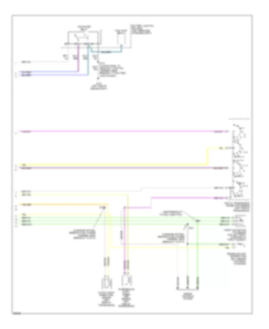
3.0L, A/T Wiring Diagram (2 of 2) for Ford Ranger 2007
List of elements for 3.0L, A/T Wiring Diagram (2 of 2) for Ford Ranger 2007:
- (in engine control sensor & fuel charge harness, near breakout to g110)
- (near breakout to fuel injector 5)
- Battery junction box (bjb) (left rear side of engine compt)
- Digital transmission range (dtr) sensor (left side of transmission)
- Engine controls system
- Engine coolant temperature (ect) sensor (top front of engine)
- Fuel pump relay
- G103 (left side of engine compt)
- Intermediate shaft speed (iss) sensor (left side of transmission)
- N r
- Output shaft speed (oss) sensor (left rear of transmission)
- Pcm power relay
- S101
- S102
- S103
- Throttle position (tp) sensor (top left front of engine, on throttle body)
4.0L
4.0L, A/T Wiring Diagram (1 of 2) for Ford Ranger 2007
List of elements for 4.0L, A/T Wiring Diagram (1 of 2) for Ford Ranger 2007:
- (in engine control sensor & fuel charge harness, near breakout to c110)
- (in engine control sensor & fuel charge harness, near breakout to heated oxygen sensor 21)
- (near breakout to g106)
- 5r55e transmission (left side of transmission)
- Anti-lock brakes system
- Battery junction box (bjb) (left rear side of engine compt)
- Bpp
- Brake pedal position switch (behind left side of dash, on brake pedal support)
- C175b
- C175e
- C175t
- C220b
- C2280a
- C2280b
- C2280c
- Can+
- Can-
- Cbb39
- Ccb15
- Cet05
- Cet06
- Cet07
- Cet18
- Cet19
- Cet34
- Cet44
- Check engine ind
- Computer data lines system
- Ect
- Epc
- Fuse 10a
- Fuse 15a
- Fuse 30a
- Fuse 5a
- G106 (top rear of engine compt)
- G107 (right rear of engine compt)
- G301 (under driver's seat)
- Gd108
- Gnd
- Harness, near breakout to instrument cluster)
- Hot at all times
- Hot in run
- Hot in run or start
- Hot in start or run
- Instrument cluster
- Iss
- Junction harness, near breakout to abs control module)
- Kapwr
- Le423
- Micro-
- Nca
- O/d off ind
- Oss
- Pcm power diode
- Powertrain control module (pcm) (right rear of engine compt)
- Prndl
- Processor
- Ptc 1a
- Re405
- Re406
- Ret04
- S100 (in engine control sensor & fuel charge harness, near breakout to powertrain control module)
- S102
- S105
- S109 (near breakout to fuel injector 6)
- S112
- S123 (near breakout to battery junction box)
- Sbb21
- Sig rtn
- Smart junction box (sjb) (right kick panel)
- Ss a
- Ssa
- Ssb
- Ssc
- Ssd
- Tcc
- Tcs
- Tft
- Tps
- Tr1
- Tr2
- Tr3a
- Tr4
- Transmission control switch (tcs) (on steering column)
- Tss
- Vdb04
- Vdb05
- Ve716
- Ve819
- Vet27
- Vet28
- Vet29
- Vet30
- Vet31
- Vet33
- Vet39
- Vpwr
- Vref
4.0L, A/T Wiring Diagram (2 of 2) for Ford Ranger 2007
List of elements for 4.0L, A/T Wiring Diagram (2 of 2) for Ford Ranger 2007:
- (in engine control sensor & fuel charge harness, near breakout to fuel injector 5)
- (in engine control sensor & fuel charge harness, near breakout to g106) s102
- Battery junction box (bjb) (left rear side of engine compt)
- Digital transmission range (dtr) sensor (left side of transmission)
- Engine controls system
- Engine coolant temperature (ect) sensor (top right front of engine)
- Fuel pump relay
- G103 (left side of engine compt)
- Intermediate shaft speed (iss) sensor (left side of transmission)
- N r
- Output shaft speed (oss) sensor (left rear of transmission)
- Pcm power relay
- S101 (in engine control sensor & fuel charge harness, near breakout to g106)
- S103
- Throttle position (tps) sensor (top front of engine, on throttle body)