TRANSMISSION
5.7L
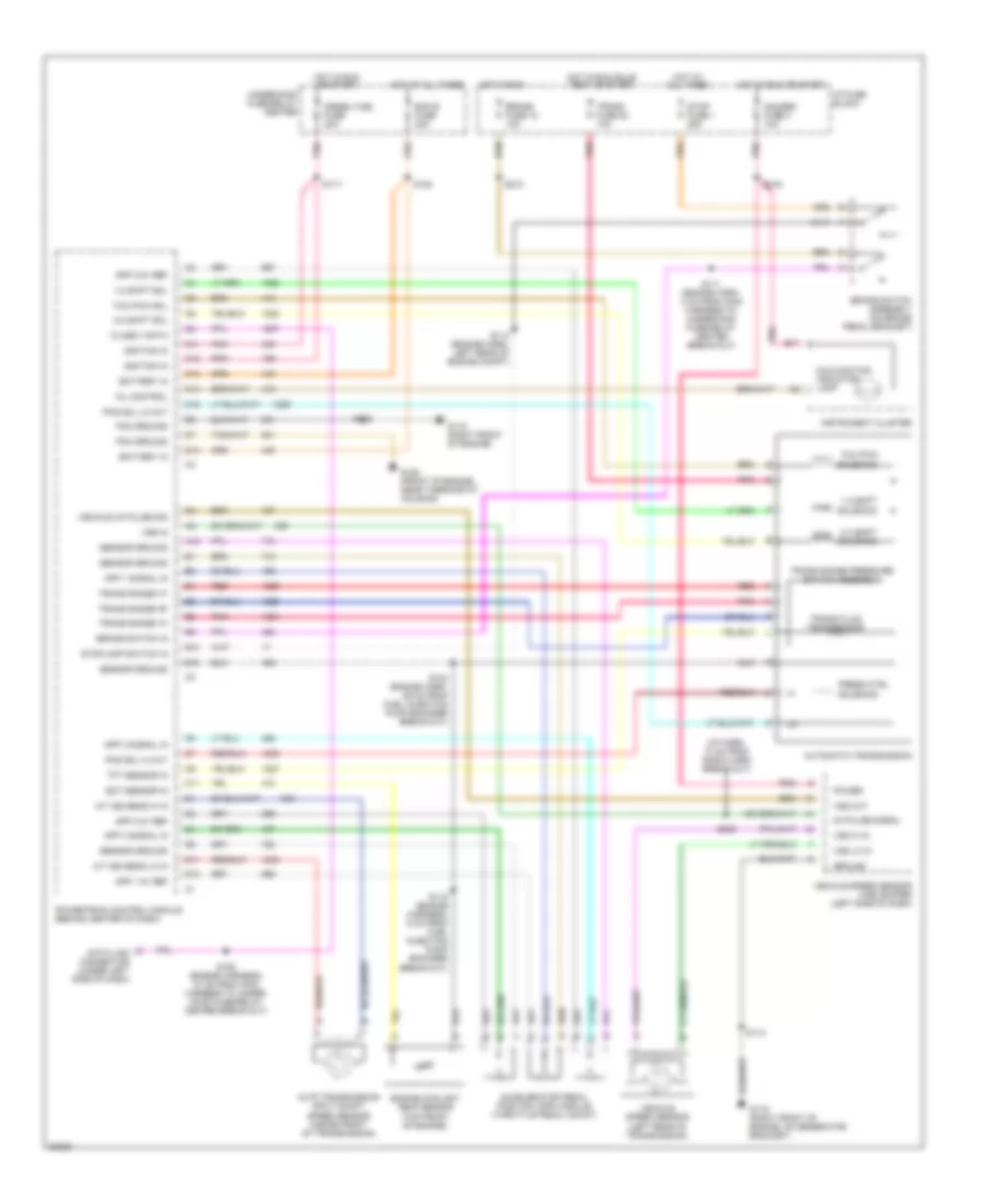
5.7L (VIN R), Transmission Wiring Diagram, 4L80-E for GMC Vandura G3500 1996

List of elements for 5.7L (VIN R), Transmission Wiring Diagram, 4L80-E for GMC Vandura G3500 1996:
- 1-2 shift
- 1-2 shift sol
- 2-3 shift sol
- 2-3 shift solenoid
- 5v reference
- A/t iss hi in
- A/t iss lo in
- Auto transmission input shaft speed sensor (inside front of transmission)
- Automatic transmission
- B17
- Battery in
- Brake fuse 18 10a
- Brake switch assembly (on brake pedal bracket)
- Brake switch input
- Data class ii
- Data link connector (under left side of dash)
- Ecm 1 fuse 20a
- Ecm b fuse 20a
- Ect sens input
- Eng 1 fuse 20a
- Engine coolant temp sensor (left side or top front of engine)
- G119 (right front of engine, on generator bracket)
- Gauges fuse 4 10a
- Hot at all times
- Hot in run
- Hot in run or start
- Hot in run, start or off
- I/p fuse block
- Ignition in
- Instrument cluster
- Malfunction indicator lamp
- Mil control
- Pcm ground
- Pcs sol hi out
- Pcs sol lo out
- Pnk
- Press ctrl
- Range signal "a"
- Range signal "b"
- Range signal "c"
- Red
- S102
- S113 (engine harn, left rear of engine compt)
- S120
- S124 or 136 (5.0l/5.7l: engine harness, 11 cm from maf sensor break-out; 7.4l: 7 cm from knock sensor break-out)
- S130
- S132
- S139 (5.0l/5.7l: engine harness, 4 cm from ect sensor break-out; 7.4l: eng harness, 21 cm from maf sensor break-out)
- S207 (i/p harness, 4 cm from tcc/brake lamp switch break-out)
- S210
- S216
- Sensor ground
- Sensor return
- Solenoid
- Tcc pwm
- Tcc pwm sol
- Throttle position sensor (mounted to side of throttle body)
- Tp sens input
- Trans fluid temp sensor
- Trans fuse 20 10a
- Trans range pressure switch assembly
- Trans temp sig in
- Underhood fuse/relay center
- Vehicle control module (vcm) (engine compt, left front fender apron)
- Vehicle speed sensor (left rear of transmission)
- Vss hi
- Vss lo
6.5L
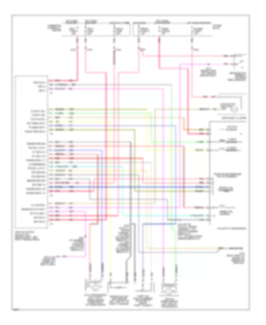
6.5L (VIN F), Transmission Wiring Diagram for GMC Vandura G3500 1996
List of elements for 6.5L (VIN F), Transmission Wiring Diagram for GMC Vandura G3500 1996:
- (i/p harn, 10 cm from radio harn break-out)
- 1-2 shift
- 1-2 shift sol
- 2-3 shift sol
- 2-3 shift solenoid
- 4k pulse signal
- A/t iss sens hi in
- A/t iss sens lo in
- A12
- Accelerator pedal position (app) module (throttle pedal mount)
- App 1 5v ref
- App 1 signal in
- App 2 5v ref
- App 2 signal in
- App 3 5v ref
- App 3 signal in
- Auto transmission input shaft speed sensor (inside front of transmission)
- Automatic transmission
- B10
- B12
- B17
- Battery in
- Brake fuse 18 10a
- Brake switch assembly (on brake pedal bracket)
- Brake switch in
- C11
- C12
- C13
- C14
- C15
- Class ii data
- D11
- D12
- D13
- Data link connector (under left side of dash)
- Diesel fuel fuse 20a
- Ecm b fuse 20a
- Ect sensor in
- Engine coolant temp sensor (top front of engine)
- G119 (right front of engine)
- G119 (right front of engine, on generator bracket)
- G125 (front of engine, near thermostat housing)
- Gauges fuse 4 10a
- Ground
- Hot at all times
- Hot in run
- Hot in run or start
- Hot in run, bulb test or start
- I/p fuse block
- Ignition in
- Instrument cluster
- Malfunction indicator lamp
- Mil control
- Pcm ground
- Pcs sol hi out
- Pcs sol lo out
- Pnk
- Power
- Powertrain control module (behind center of dash)
- Press ctrl
- Red
- S102
- S111 (engine harn, 4 cm from main harness to underhood fuse/relay center break-out)
- S112
- S114 (engine harn, left rear of engine compt)
- S115 (engine harness, 6 cm from fuel injection pump encoder break-out)
- S117
- S120
- S124 (engine harn, 29 cm from fuel injection pump encoder break-out)
- S150 (engine harness, 27 cm from main harness to under- hood fuse/relay center break-out)
- S210
- S216
- S239
- Sensor ground
- Solenoid
- Stop fuse 1 25a
- Stoplamp switch in
- Tcc pwm
- Tcc pwm sol
- Tft sensor in
- Trans fluid temp sensor
- Trans fuse 20 10a
- Trans range "a"
- Trans range "b"
- Trans range "c"
- Trans range pressure switch assembly
- Underhood fuse/relay center
- Vehicle 4k pulse sig
- Vehicle speed sensor (left rear of transmission)
- Vehicle speed sensor (vss) buffer (left side of dash)
- Vss hi in
- Vss in
- Vss lo in
- Vss out
7.4L
7.4L (VIN J), Transmission Wiring Diagram, 4L80-E for GMC Vandura G3500 1996
List of elements for 7.4L (VIN J), Transmission Wiring Diagram, 4L80-E for GMC Vandura G3500 1996:
- 1-2 shift
- 1-2 shift sol
- 2-3 shift sol
- 2-3 shift solenoid
- 5v reference
- A/t iss hi in
- A/t iss lo in
- Auto transmission input shaft speed sensor (inside front of transmission)
- Automatic transmission
- B17
- Battery in
- Brake fuse 18 10a
- Brake switch assembly (on brake pedal bracket)
- Brake switch input
- Data class ii
- Data link connector (under left side of dash)
- Ecm 1 fuse 20a
- Ecm b fuse 20a
- Ect sens input
- Eng 1 fuse 20a
- Engine coolant temp sensor (left side or top front of engine)
- G119 (right front of engine, on generator bracket)
- Gauges fuse 4 10a
- Hot at all times
- Hot in run
- Hot in run or start
- Hot in run, start or off
- I/p fuse block
- Ignition in
- Instrument cluster
- Malfunction indicator lamp
- Mil control
- Pcm ground
- Pcs sol hi out
- Pcs sol lo out
- Pnk
- Press ctrl
- Range signal "a"
- Range signal "b"
- Range signal "c"
- Red
- S102
- S113 (engine harn, left rear of engine compt)
- S120
- S124 or 136 (5.0l/5.7l: engine harness, 11 cm from maf sensor break-out; 7.4l: 7 cm from knock sensor break-out)
- S130
- S132
- S139 (5.0l/5.7l: engine harness, 4 cm from ect sensor break-out; 7.4l: eng harness, 21 cm from maf sensor break-out)
- S207 (i/p harness, 4 cm from tcc/brake lamp switch break-out)
- S210
- S216
- Sensor ground
- Sensor return
- Solenoid
- Tcc pwm
- Tcc pwm sol
- Throttle position sensor (mounted to side of throttle body)
- Tp sens input
- Trans fluid temp sensor
- Trans fuse 20 10a
- Trans range pressure switch assembly
- Trans temp sig in
- Underhood fuse/relay center
- Vehicle control module (vcm) (engine compt, left front fender apron)
- Vehicle speed sensor (left rear of transmission)
- Vss hi
- Vss lo