TRANSMISSION
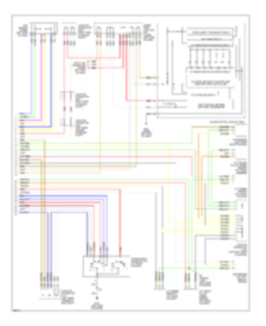
A/T Wiring Diagram, Except Hybrid (1 of 2) for Honda Civic Hybrid 2007

List of elements for A/T Wiring Diagram, Except Hybrid (1 of 2) for Honda Civic Hybrid 2007:
A/T Wiring Diagram, Except Hybrid (2 of 2) for Honda Civic Hybrid 2007
List of elements for A/T Wiring Diagram, Except Hybrid (2 of 2) for Honda Civic Hybrid 2007:
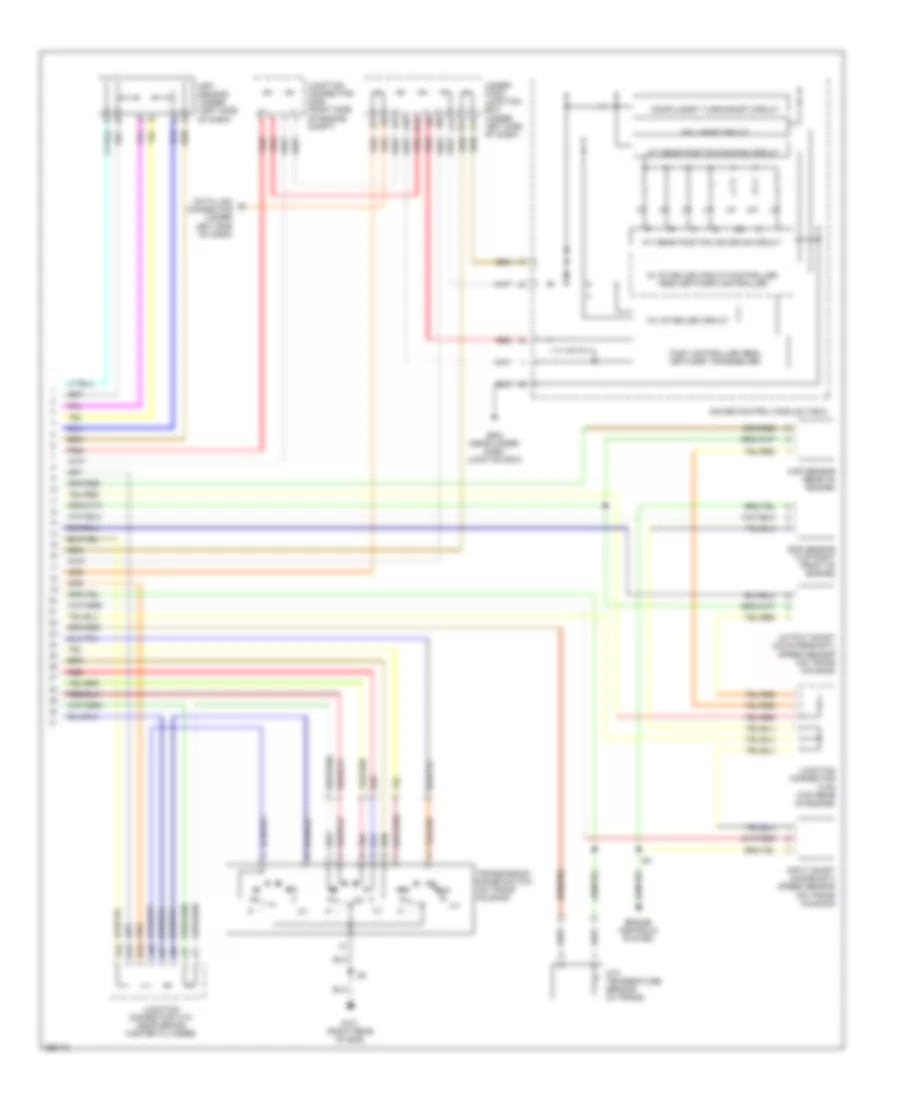
A/T Wiring Diagram, Hybrid (1 of 2) for Honda Civic Hybrid 2007
List of elements for A/T Wiring Diagram, Hybrid (1 of 2) for Honda Civic Hybrid 2007:
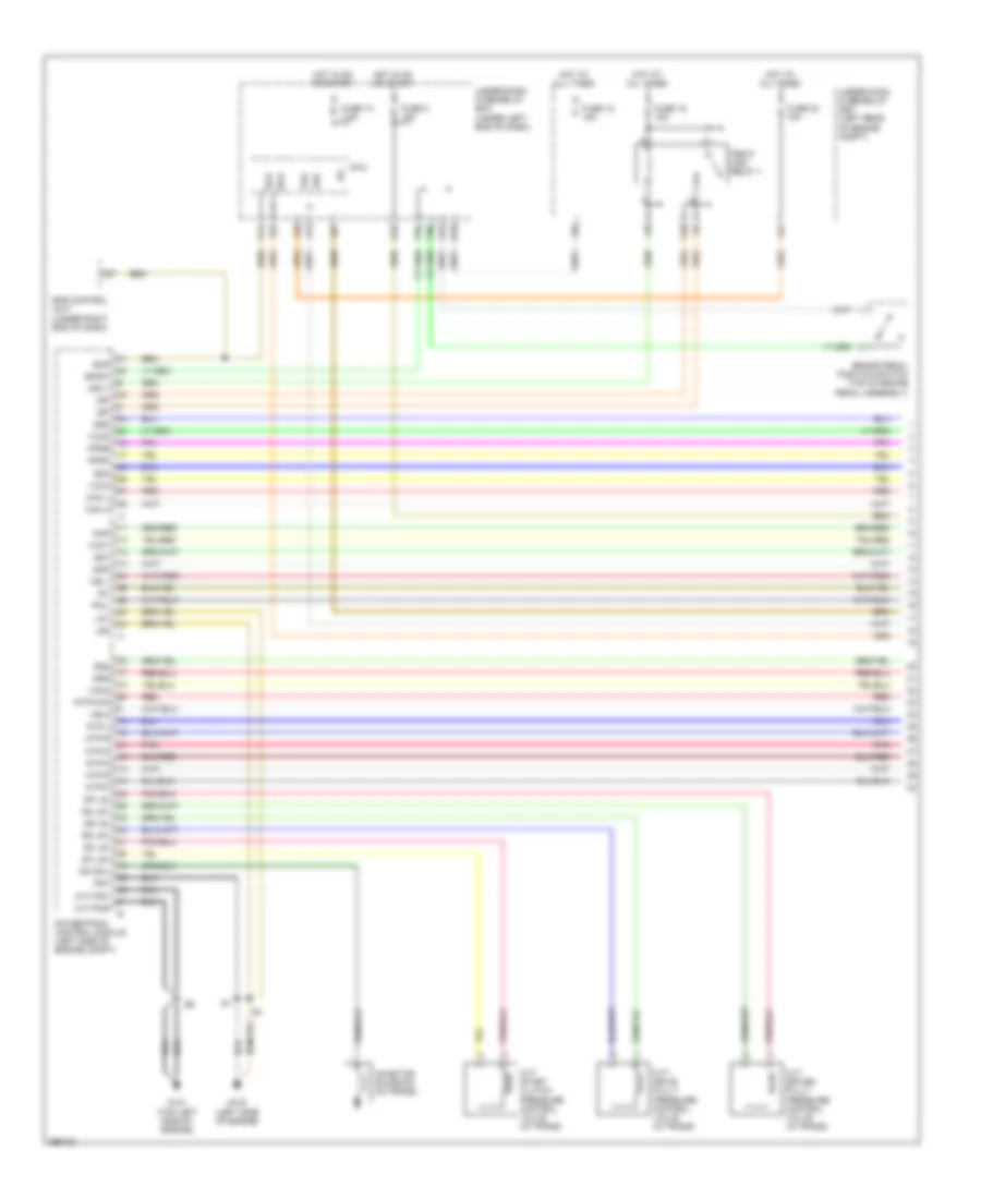
A/T Wiring Diagram, Hybrid (2 of 2) for Honda Civic Hybrid 2007
List of elements for A/T Wiring Diagram, Hybrid (2 of 2) for Honda Civic Hybrid 2007: