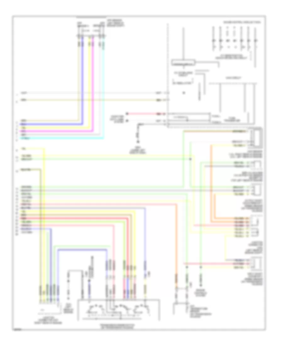
TRANSMISSION
Transmission Wiring Diagram, Except Hybrid (1 of 2) for Honda Civic Hybrid 2013

List of elements for Transmission Wiring Diagram, Except Hybrid (1 of 2) for Honda Civic Hybrid 2013:
- (under left side of dash) brake pedal position switch
- 2nd clutch trans- mission fluid pressure switch a (on trans- mission housing)
- 3rd clutch trans- mission fluid pressure switch b
- A/t clutch pressure control solenoid valve a (on trans- mission housing)
- A/t clutch pressure control solenoid valve b (on trans- mission housing)
- A/t clutch pressure control solenoid valve c (on trans- mission housing)
- A13
- A28
- A29
- A35
- A36
- A42
- A45
- A46
- B10
- B11
- B19
- B21
- B23
- B24
- B25
- B26
- B27
- B28
- B29
- B30
- B31
- B32
- B35
- B36
- B38
- B39
- B44
- B45
- B48
- C10
- C13
- C15
- C16
- C20
- C21
- C23
- C24
- C25
- C32
- C401
- Computer data lines system
- D28
- Dlc (under left side of dash)
- Ecm/pcm (left side of engine compt)
- Fuse 17 15a
- Fuse 21 15a
- Fuse 29 10a
- Fuse 4 15a
- Fuse 5 7.5a
- Fuse 7 15a
- G101 (left rear of engine)
- Hot at all times
- Hot in on or start
- Instrument cluster system
- Line pressure solenoid valve a (left front of trans- mission)
- Pgm-fi main relay 1
- Red
- Shift solenoid valves a, b, c & d (on transmission housing)
- Under-dash fuse/relay box (under left end of dash)
- Under-hood fuse/relay box (left rear of engine compt)
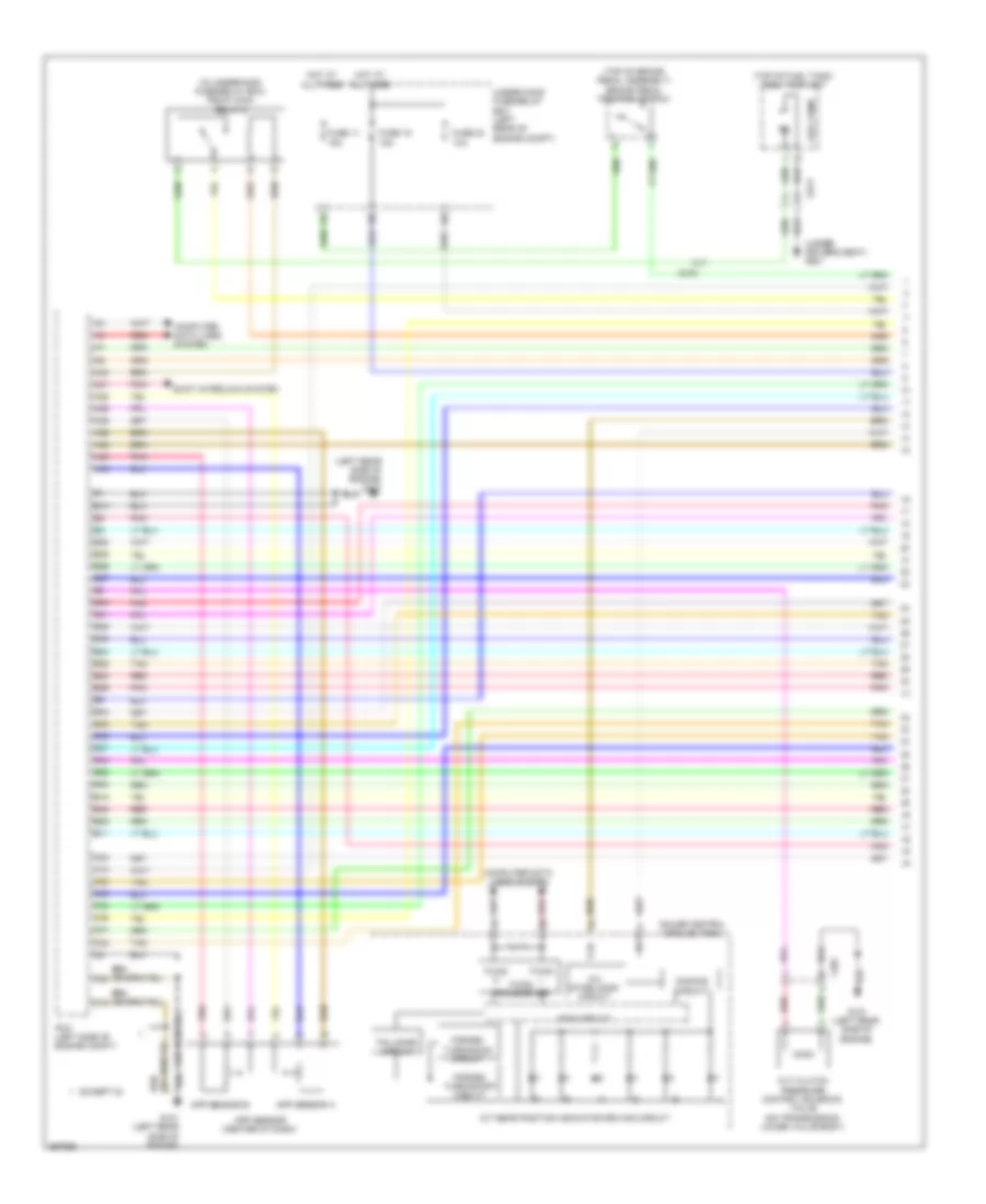
Transmission Wiring Diagram, Except Hybrid (2 of 2) for Honda Civic Hybrid 2013
List of elements for Transmission Wiring Diagram, Except Hybrid (2 of 2) for Honda Civic Hybrid 2013:
- 10v stabilizing circuit
- 5v regulator
- A/t gear position indicator driving circuit
- App
- App sensor (left rear of app sensor b
- Atf temperature sensor (on transmission housing)
- C401
- C405
- Computer data lines system
- Dimming circuit
- Egr valve & egr valve position sensor (except si) (top left rear of engine)
- Engine compt)
- Engine controls system
- F-can h
- F-can l
- F-can transceiver
- G101 (left rear of engine)
- G503 (under left side of dash)
- Gauge control module (tach)
- Input shaft (mainshaft) speed sensor (on transmission housing)
- Junction connector c404 (left rear of engine compt)
- Junction connector c407 (right rear of engine)
- Main circuit
- Map sensor (1.8l: right rear of engine) (2.4l: left rear of engine)
- Output shaft (countershaft) speed sensor (on transmission housing)
- Pnk
- Red
- Sensor a
- Starting/ charging system
- Transmission range switch (on transmission housing)
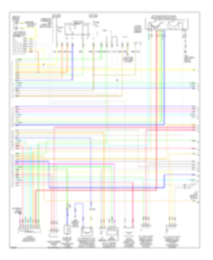
Transmission Wiring Diagram, Hybrid (1 of 3) for Honda Civic Hybrid 2013
List of elements for Transmission Wiring Diagram, Hybrid (1 of 3) for Honda Civic Hybrid 2013:
- (in underhood fuse/relay box) pgm-fi main relay 2
- (left rear side of engine) g101
- (top of brake pedal assembly) brake pedal position switch
- (top of fuel tank) fuel tank unit
- (under driver's seat) g601
- 10v stabilizing circuit
- A/t gear position indicator driving circuit
- A21
- A28
- A29
- A35
- A36
- A40
- A42
- A45
- A46
- App sensor (center of dash)
- App sensor a
- App sensor b
- B10
- B11
- B15
- B22
- B23
- B24
- B25
- B26
- B27
- B28
- B29
- B33
- B34
- B35
- B36
- B37
- B38
- B39
- B40
- B41
- B42
- B43
- B44
- B48
- C10
- C15
- C20
- C216
- C223
- C23
- C24
- C301
- C34
- C35
- C41
- C42
- C49
- Computer data lines system
- Cvt clutch pressure control solenoid valve (on transmission lower valve body)
- Dimming circuit
- Except si
- F-can h
- F-can l
- F-can transceiver
- Fail-safe circuit
- Forced turning-off circuit
- Forced turning-on circuit
- Fuel pump
- Fuse 11 15a
- Fuse 15 15a
- Fuse 23 10a
- G101 (left rear side of engine)
- Gauge control module (tach)
- Hot at all times
- Main circuit
- Pcm (left side of engine compt)
- Pnk
- Red
- Shift interlock system
- Tan
- Under-hood fuse/relay box (left rear of engine compt)
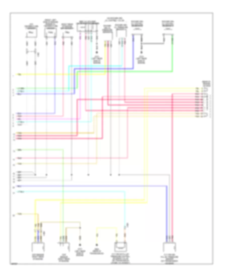
Transmission Wiring Diagram, Hybrid (2 of 3) for Honda Civic Hybrid 2013
List of elements for Transmission Wiring Diagram, Hybrid (2 of 3) for Honda Civic Hybrid 2013:
- (left rear of engine compt) j/c c302
- (on transmission housing) transmission range switch
- (rear of engine) j/c c010
- C13
- C20
- C25
- C301
- Computer data lines system
- Cvt driven pulley pressure control solenoid valve (on transmission lower valve body)
- Cvt input shaft (drive pulley) speed sensor (bottom of transmission housing)
- Cvt output shaft (driven pulley) speed sensor (top of transmission housing)
- D23
- D28
- Engine controls system
- Evap canister purge valve (top rear of engine)
- Exterior lights system
- Fuse 15a
- Fuse 7.5a
- G101 (left rear side of engine)
- G902 (rear of trans- mission)
- Gauge control module (speedo)
- Hot in on or start
- Iat sensor
- Inhibitor solenoid (on transmission lower valve body)
- J/c c010 (rear of engine)
- J/c c302 (left rear of engine compt)
- Maf sensor
- Maf/iat sensor (on engine air intake duct)
- Micu
- P r
- Pgm-fi main relay 1
- Pnk
- Red
- Tan
- Under-dash fuse/relay box (under left end of dash)
- Vehicle speed sensor (in transmission)
Transmission Wiring Diagram, Hybrid (3 of 3) for Honda Civic Hybrid 2013
List of elements for Transmission Wiring Diagram, Hybrid (3 of 3) for Honda Civic Hybrid 2013:
- (front left side of engine) engine oil temperature sensor
- (on rocker arm oil control valve)
- (rear of engine) j/c c010
- (right rear of engine) ect sensor 1
- Atf temperature sensor
- C301
- C303
- Ckp sensor (right rear of engine)
- Cmp sensor (right rear of engine)
- Cvt drive pulley pressure control solenoid valve (on transmission lower valve body)
- Cvt driven pulley pressure sensor (on transmission housing)
- Egr valve & egr valve position sensor
- G101 (left rear side of engine)
- G902 (rear of transmission)
- Pnk
- Rocker arm oil control solenoid a
- Rocker arm oil control solenoid b
- Rocker arm oil pressure sensor a
- Rocker arm oil pressure sensor b
- Tan