TRANSMISSION
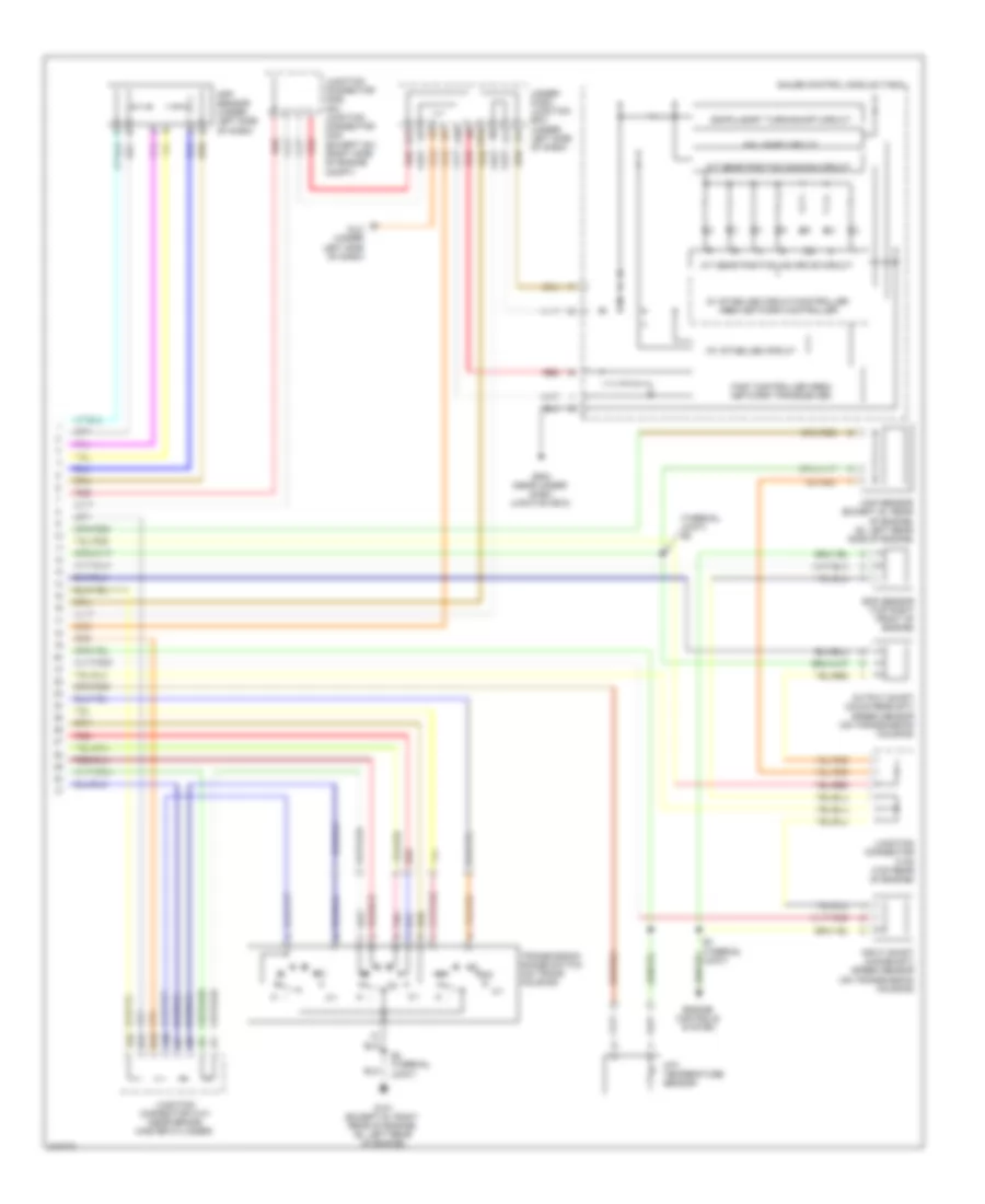
Transmission Wiring Diagram, Except Hybrid (1 of 2) for Honda Civic Si 2009

List of elements for Transmission Wiring Diagram, Except Hybrid (1 of 2) for Honda Civic Si 2009:
- 2 door
- 2nd clutch trans- mission fluid pressure switch (on trans- mission housing)
- 3rd clutch trans- mission fluid pressure switch (on trans- mission housing)
- A/t clutch pressure control solenoid valve a (on trans- mission housing)
- A/t clutch pressure control solenoid valve b (on trans- mission housing)
- A/t clutch pressure control solenoid valve c (on trans- mission housing)
- Apsa
- Apsb
- Atft
- Atp-d
- Atp-d3
- Atp-fwd
- Atp-n
- Atp-p
- Atp-r
- Atp-rvs
- Atp2-1
- Bksw
- Brake pedal position switch (under left side of dash)
- Can h
- Can l
- Except gx
- F11
- F24
- F25
- F29
- F30
- F31
- Fuse 10 7.5a
- Fuse 12 15a
- Fuse 19 15a
- Fuse 2 15a
- Fuse 23 10a
- G101 (except si: right rear of engine) (si: left rear of engine)
- G16
- Hot at all times
- Hot in on or start
- Ig1
- Igp
- Lg1
- Lg2
- Lsa
- Lsb
- Lsc
- Map
- Micu
- Mrly
- Op2sw
- Op3sw
- Pcm (gx) ecm/pcm (except gx) (left side of engine compt)
- Pg1
- Pg2
- Pgm-fi main relay 1
- Poil
- Red
- S2 (thermal joint)
- S3 (thermal joint)
- Scs
- Sg1
- Sg2
- Sg4
- Sg5
- Sha
- Shb
- Shc
- Shd
- Shift control solenoid valves a, b, c & d
- Starter cut relay
- Under-dash fuse/relay box (under left end of dash)
- Under-hood fuse/relay box (left side of engine compt)
- Vbu
- Vcc1
- Vcc2
- Vcc4
- Vcc5
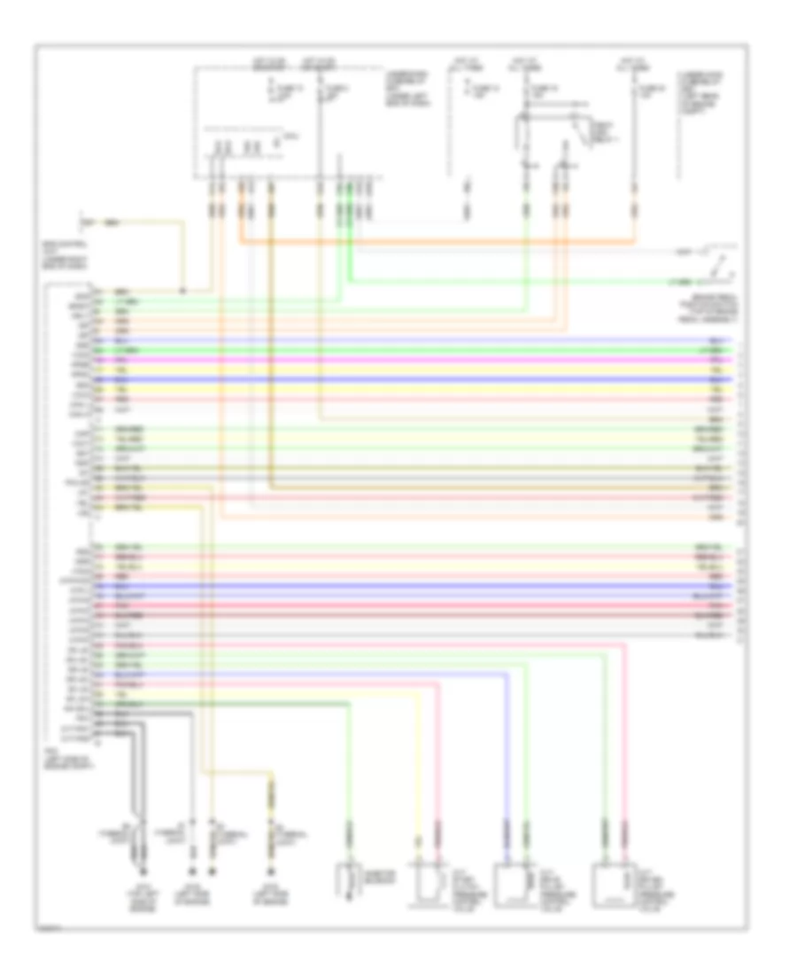
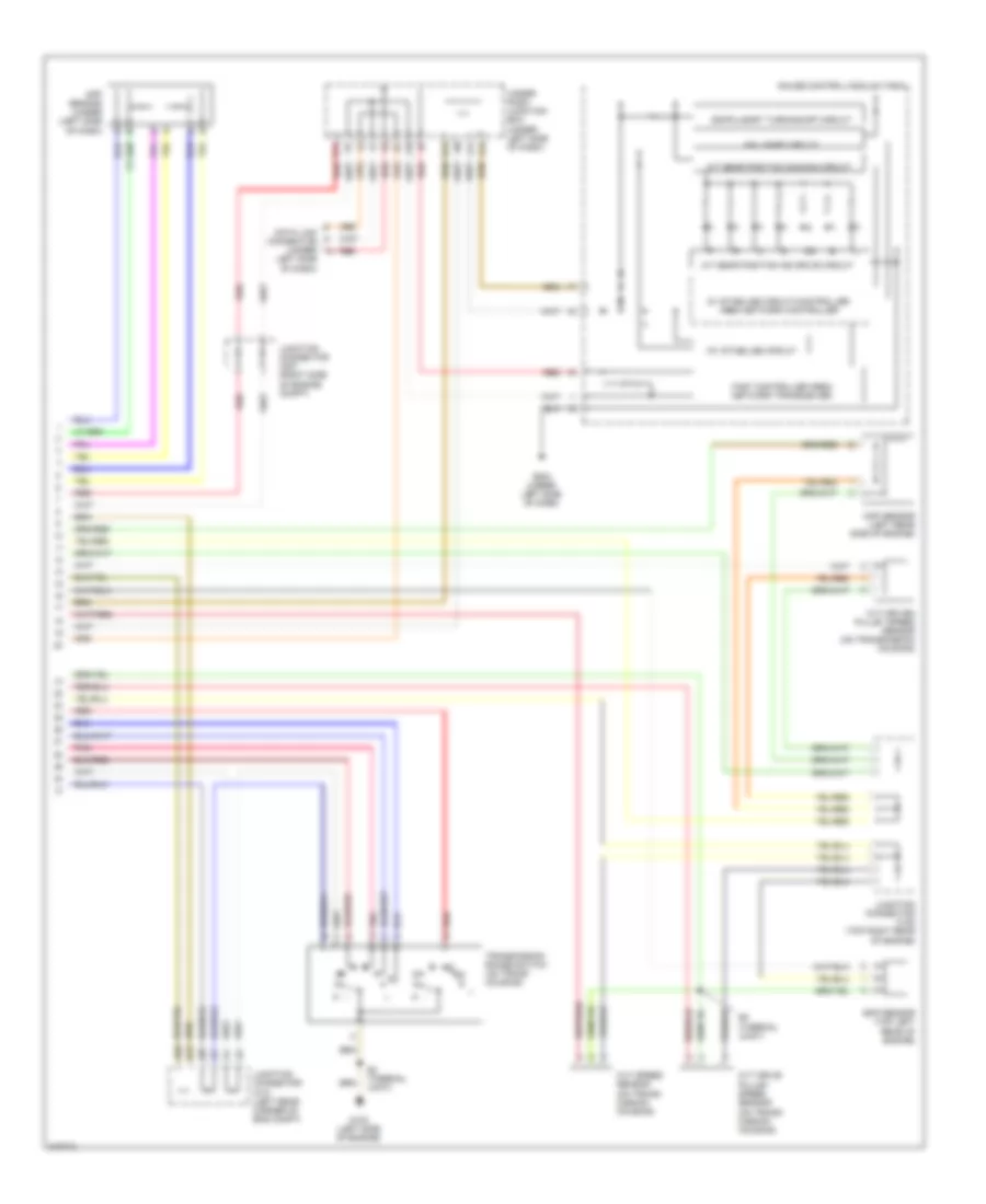
Transmission Wiring Diagram, Except Hybrid (2 of 2) for Honda Civic Si 2009
List of elements for Transmission Wiring Diagram, Except Hybrid (2 of 2) for Honda Civic Si 2009:
- (thermal joint) s5
- 10v stabilize circuit
- 2-1
- 5v stabilize circuit/controller area network controller
- A/t gear position dimming circuit
- A/t gear position ind drive circuit
- A20
- A22
- App sensor (under left side of dash)
- Atf temperature sensor
- B17
- B19
- Compulsory turning-off circuit
- Dlc (under left side of dash)
- Engine controls system
- Eop sensor (top right front of engine)
- Fail-safe circuit
- Fast controller area network transceiver
- G101 (except si: right rear of engine) (si: left rear of engine)
- G14
- G504 (near under- dash junction box)
- Gauge control module (tach)
- Input shaft (mainshaft) speed sensor (on transmission housing)
- J10
- J11
- J14
- Junction connector c101 (near brake master cylinder)
- Junction connector c105 (top rear of engine)
- Junction connector c206 (gx) junction connector c207 (except gx) (right side of engine compt)
- K14
- Map sensor (except si: rear of engine) (si: left rear side of engine)
- Output shaft (countershaft) speed sensor (on transmission housing)
- Pnk
- Red
- S2 (thermal joint)
- S4 (thermal joint)
- Transmission range switch (on trans housing)
- Under- dash junction box (under left side of dash)
Transmission Wiring Diagram, Hybrid (1 of 2) for Honda Civic Si 2009
List of elements for Transmission Wiring Diagram, Hybrid (1 of 2) for Honda Civic Si 2009:
- Apsa
- Apsb
- Atp-d
- Atp-fwd
- Atp-l
- Atp-n
- Atp-p
- Atp-r
- Atp-s
- Bksw
- Brake pedal position switch (top of brake pedal assembly)
- Can h
- Can l
- Cvt drive pulley pressure control valve
- Cvt driven pulley pressure control valve
- Cvt start clutch pressure control valve
- Cvt-pg1
- Cvt-pg2
- Dn ls+
- Dn ls-
- Dr ls+
- Dr ls-
- Eps control unit (under right end of dash)
- F10
- F11
- F24
- F25
- F30
- F31
- Fuse 10 7.5a
- Fuse 12 15a
- Fuse 19 15a
- Fuse 2 15a
- Fuse 23 10a
- G101 (top left side of engine)
- G102 (left side of engine)
- G16
- Hot at all times
- Hot in on or start
- Ig1
- Igp
- Inh sol
- Inhibitor solenoid
- Lg1
- Lg2
- Map
- Micu
- Mrly
- Ndn
- Ndr
- Pcm (left side of engine compt)
- Pg1
- Pgm-fi main relay 1
- Pnk
- Poilcs
- Red
- S1 (thermal joint)
- S3 (thermal joint)
- S4 (thermal joint)
- S6 (thermal joint)
- Sc ls+
- Sc ls-
- Scs
- Sg1
- Sg2
- Sg4
- Sg5
- Under-dash fuse/relay box (under left end of dash)
- Under-hood fuse/relay box (left rear of engine compt)
- Vbu
- Vcc1
- Vcc2
- Vcc4
- Vcc5
- Vel
Transmission Wiring Diagram, Hybrid (2 of 2) for Honda Civic Si 2009
List of elements for Transmission Wiring Diagram, Hybrid (2 of 2) for Honda Civic Si 2009:
- 10v stabilize circuit
- 5v stabilize circuit/controller area network controller
- A/t gear position dimming circuit
- A/t gear position ind drive circuit
- A22
- App sensor (under (left side of dash)
- B17
- Compulsory turning-off circuit
- Cvt drive pulley speed sensor (on trans- mission housing)
- Cvt driven pulley speed sensor (on transmission housing)
- Cvt speed sensor (on trans- mission housing)
- Data link connector (under
- Eop sensor (top left rear of engine)
- Fail-safe circuit
- Fast controller area network transceiver
- G102 (left side of engine)
- G14
- G504 (under left side of dash)
- Gauge control module (tach)
- J10
- J11
- J14
- Junction connector c101 (left rear corner of eng compt)
- Junction connector c105 (top right rear of engine)
- Junction connector c207 (right side of engine compt)
- K14
- Left side of dash)
- Map sensor (left rear side of engine)
- Pnk
- Red
- S2 (thermal joint)
- S5 (thermal joint)
- Transmission range switch (on trans housing)
- Under- dash junction box (under left side of dash)