TRANSMISSION
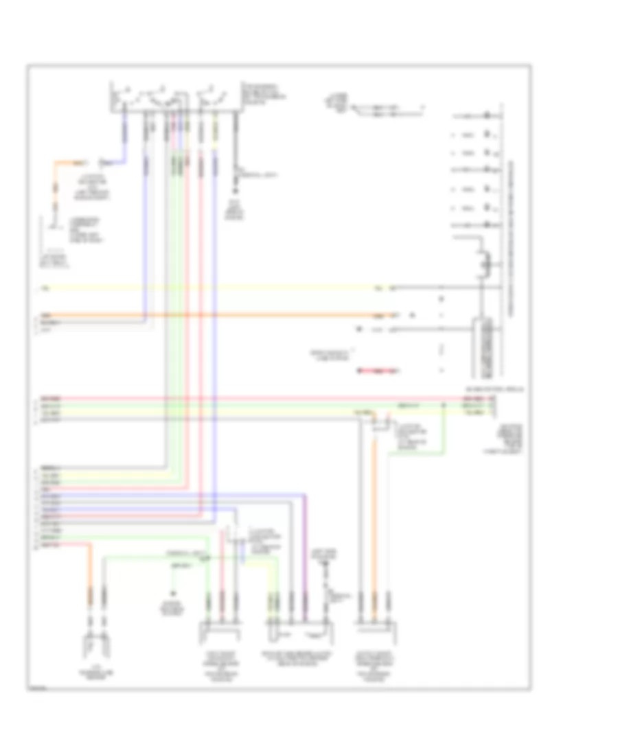
Transmission Wiring Diagram (1 of 2) for Honda CR-V EX 2008

List of elements for Transmission Wiring Diagram (1 of 2) for Honda CR-V EX 2008:
Transmission Wiring Diagram (2 of 2) for Honda CR-V EX 2008
List of elements for Transmission Wiring Diagram (2 of 2) for Honda CR-V EX 2008: