TRANSMISSION
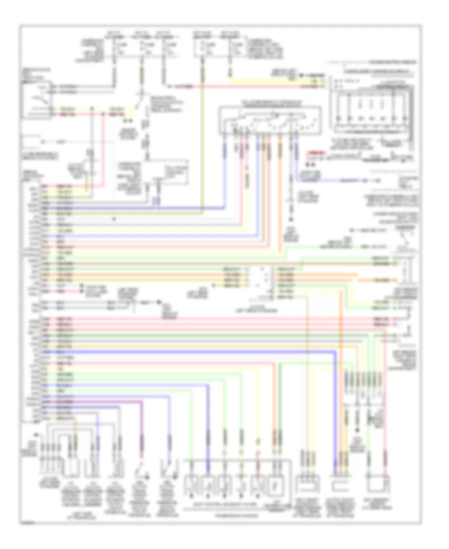
Transmission Wiring Diagram for Honda Element EX 2009
List of elements for Transmission Wiring Diagram for Honda Element EX 2009:
 English
Transmission Wiring Diagram for Honda Element EX 2009
List of elements for Transmission Wiring Diagram for Honda Element EX 2009: