TRANSMISSION
A/T Wiring Diagram, 5 Speed (1 of 2) for Honda Odyssey Touring 2013

List of elements for A/T Wiring Diagram, 5 Speed (1 of 2) for Honda Odyssey Touring 2013:
- A16
- A17
- A18
- A19
- A24
- A25
- A26
- A27
- A32
- A48
- A49
- Apsa
- Apsb
- Atpd
- Atpfwd
- Atpl
- Atpn
- Atpp
- Atpr
- Atprvs
- B10
- B21
- B34
- B35
- B36
- B37
- B38
- B42
- B44
- Bksw
- Bkswnc
- C101
- C107
- C12
- C16
- C17
- C18
- C19
- C20
- C21
- C212
- C25
- C26
- C27
- C28
- C33
- C37
- C38
- C46
- Computer data lines system
- D3sw
- Driver's under-dash fuse/relay box (left end of dash)
- F-can-h
- F-can-l
- F10
- F21
- Fuse 10 15a
- Fuse 10a
- Fuse 15a
- Fuse 20a
- Fuse 7.5a
- G101 (front of right cylinder head)
- Hot at all times
- Hot in on or start
- Ig1
- Ignition coil relay
- Igp
- J/c c102 (top right side of engine)
- J/c c104 (top right side of engine)
- J/c c105 (top right side of engine)
- Lsa
- Lsb
- Lsc
- Map
- Map sensor
- Mrly
- Op2sw
- Op3sw
- Op4sw
- Output shaft (countershaft) speed sensor (on transaxle)
- Pcm (right rear of engine compt)
- Pg 2
- Pgm-fi main relay 1
- Pnk
- Red
- Scs
- Sg1
- Sg2
- Sg3
- Sg4
- Sha
- Shb
- Shc
- Shd
- Shift control solenoid valve a (left side of transaxle)
- Shift control solenoid valve b (left side of transaxle)
- Shift control solenoid valve c (left side of transaxle)
- Shift control solenoid valve d
- Starting/ charging system
- Tan
- Tatf
- Transmission range switch (left side of transaxle)
- Trunk, tailgate, fuel doors system
- Under-hood fuse/relay box (right rear of engine compt)
- Vbsol
- Vbsol2
- Vcc1
- Vcc2
- Vcc3
- Vcc4
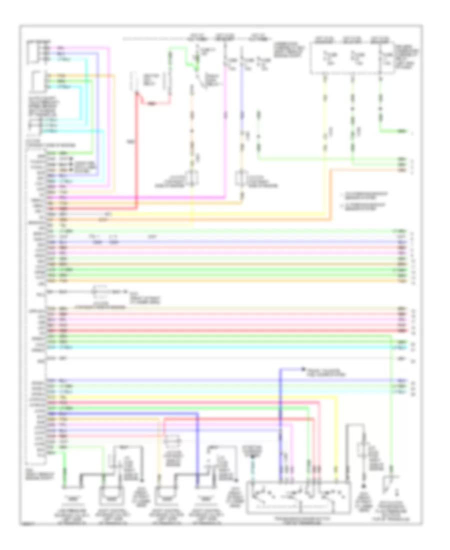
A/T Wiring Diagram, 5 Speed (2 of 2) for Honda Odyssey Touring 2013
List of elements for A/T Wiring Diagram, 5 Speed (2 of 2) for Honda Odyssey Touring 2013:
- (front of right cylinder head) g101
- (on brake pedal bracket) brake pedal position switch
- (right side of dash) center junction box
- (top of accelerator pedal assembly) app sensor
- 2nd clutch transmission fluid pressure switch a (bottom of transaxle)
- 3rd clutch transmission fluid pressure switch b (on transaxle)
- 4th clutch transmission fluid pressure switch (top of transaxle)
- A/t clutch pressure control solenoid valve a (top of transaxle)
- A/t clutch pressure control solenoid valve b (top of transaxle)
- A/t clutch pressure control solenoid valve c (top of transaxle)
- Atf temperature sensor (on transaxle)
- C205
- C210
- C212
- Computer data lines system
- Control circuits
- D3 switch
- Exterior lights system
- F-can
- Fuse 2
- Fuse 9 7.5a
- G101 (front of right cylinder head)
- G401 (left side of dash)
- G403 (center of dash)
- Gauge control module
- Horns system
- Hot at all times
- Input shaft (mainshaft) speed sensor (on transaxle)
- J/c c102 (top right side of engine)
- J/c c104 (top right side of engine)
- J/c c105 (top right side of engine)
- Main under-hood fuse box (left side of engine compt)
- Multi-
- Pnk
- Red
- Shift lever connector
- Stop/ horn hazard 30a
- Tan
- Transceiver
- W/ parking & backup sensor system
- W/o parking & backup sensor system
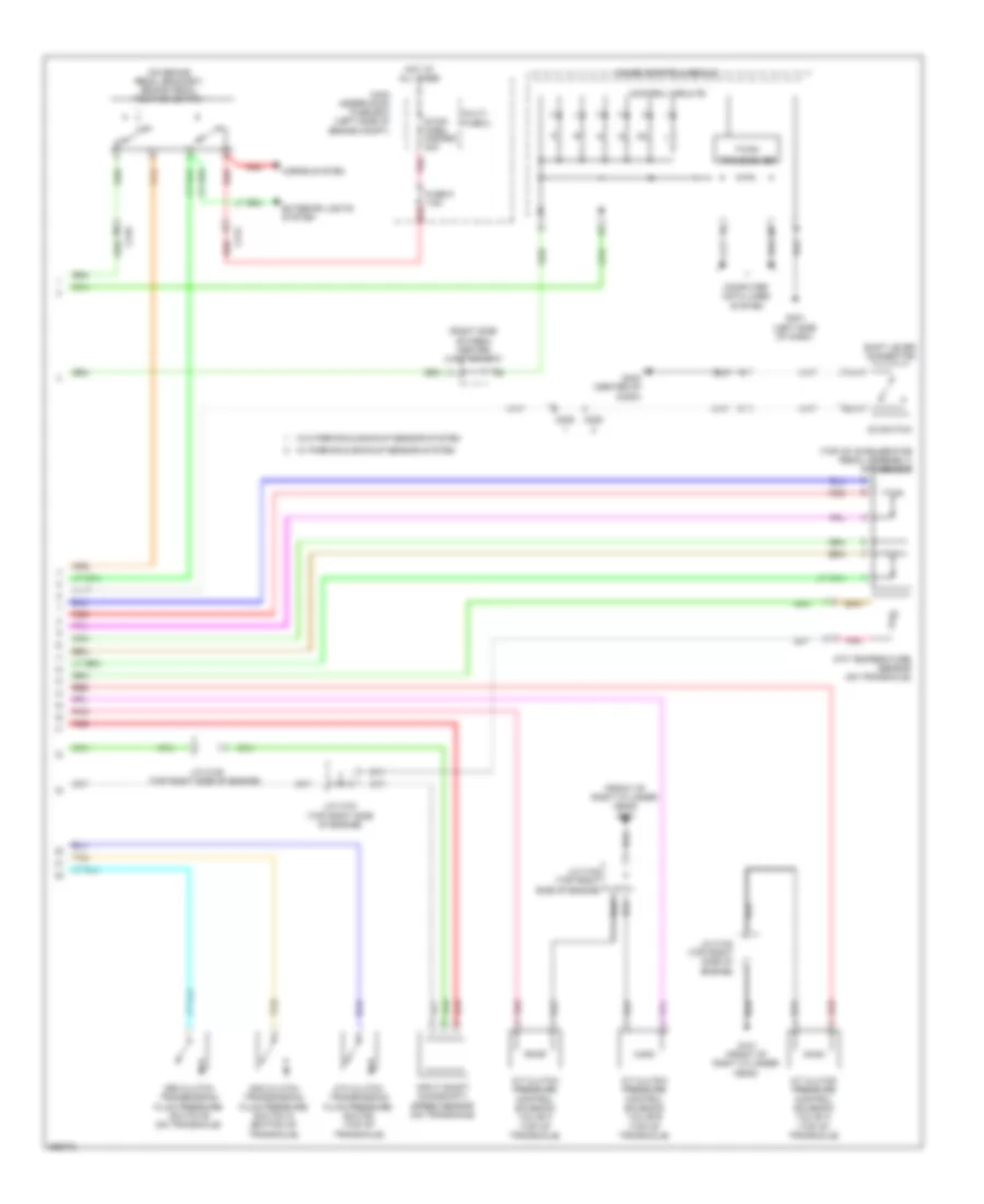
A/T Wiring Diagram, 6 Speed (1 of 2) for Honda Odyssey Touring 2013
List of elements for A/T Wiring Diagram, 6 Speed (1 of 2) for Honda Odyssey Touring 2013:
- 6th clutch transmission fluid pressure switch e (top of transaxle)
- A16
- A17
- A18
- A19
- A24
- A25
- A26
- A27
- A32
- A48
- A49
- Apsa
- Apsb
- Atpd
- Atpfwd
- Atpl
- Atpn
- Atpp
- Atpr
- Atprvs
- B10
- B21
- B34
- B35
- B36
- B37
- B38
- B42
- B44
- Bksw
- Bkswnc
- C101
- C12
- C14
- C15
- C16
- C17
- C18
- C19
- C20
- C205
- C21
- C210
- C212
- C25
- C26
- C27
- C28
- C31
- C33
- C35
- C37
- C38
- C43
- C46
- Computer data lines system
- D4sw
- Driver's under-dash fuse/relay relay (left end of dash)
- F-can-h
- F-can-l
- F10
- F21
- Fuse 10 15a
- Fuse 10a
- Fuse 15a
- Fuse 20a
- Fuse 7.5a
- G101 (front of right cylinder head)
- Hot at all times
- Hot in on or start
- Ig1
- Ignition coil relay
- Igp
- J/c c102 (top right side of engine)
- J/c c104 (top right side of engine)
- J/c c105 (top right side of engine)
- Line pressure solenoid valve a (left side of transaxle)
- Lsa
- Lsb
- Lsc
- Lsd
- Map
- Map sensor
- Mrly
- Op2sw
- Op3sw
- Op4sw
- Op5sw
- Op6sw
- Output shaft (countershaft) speed sensor (bottom rear of transaxle)
- Pcm (right rear of engine compt)
- Pg 2
- Pgm-fi main relay 1
- Pla
- Pnk
- R p
- Red
- Scs
- Sensor system
- Sg1
- Sg2
- Sg3
- Sg4
- Sg6
- Sha
- Shb
- Shc
- Shift control solenoid valve a (left side of transaxle)
- Shift control solenoid valve b (left side of transaxle)
- Shift control solenoid valve c (left side of transaxle)
- Starting/ charging system
- Tan
- Tatf
- Transmission range switch (top of transaxle)
- Trunk, tailgate, fuel doors system
- Under-hood fuse/relay box (right rear of engine compt)
- Vbsol
- Vbsol2
- Vcc1
- Vcc2
- Vcc3
- Vcc4
- W/ parkinkg backup
- W/o parkinkg backup
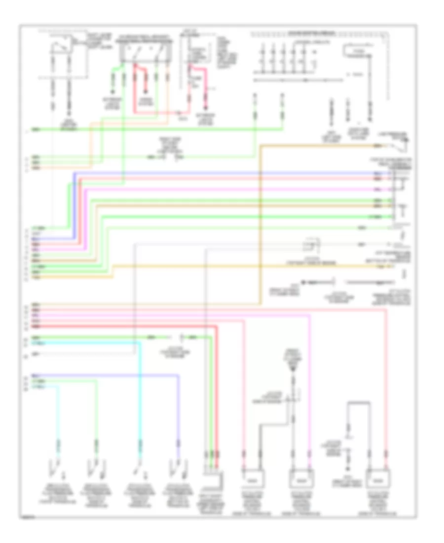
A/T Wiring Diagram, 6 Speed (2 of 2) for Honda Odyssey Touring 2013
List of elements for A/T Wiring Diagram, 6 Speed (2 of 2) for Honda Odyssey Touring 2013:
- (front of right cylinder head) g101
- (on brake pedal bracket) brake pedal position switch
- (right side of dash) center junction box
- (top of accelerator pedal assembly) app sensor
- 2nd clutch transmission fluid pressure switch a (side of transaxle)
- 3rd clutch transmission fluid pressure switch b (top of transaxle)
- 4th clutch transmission fluid pressure switch c (bottom of transaxle)
- 5th clutch transmission fluid pressure switch d (side of transaxle)
- A/t clutch pressure control solenoid valve a (side of transaxle)
- A/t clutch pressure control solenoid valve b (side of transaxle)
- A/t clutch pressure control solenoid valve c (side of transaxle)
- A/t clutch pressure control solenoid valve d (side of transaxle)
- Atf temperature sensor (bottom of transaxle)
- C212
- Computer data lines system
- Control circuits
- D4 switch
- Exterior lights system
- F-can
- Fuse 20a
- G101 (front of right cylinder head)
- G401 (left side of dash)
- G403 (center of dash)
- Gauge control module
- Horns system
- Hot at all times
- Input shaft (mainshaft) speed sensor (left side of transaxle)
- J/c c102 (top right side of engine)
- J/c c104 (top right side of engine)
- J/c c105 (top right side of engine)
- Line pressure switch
- Main under- hood fuse/ relay box (left side of engine compt)
- Pnk
- Red
- Shift lever connector (under shift lever)
- Stop & horn hazard 30a
- Tan
- Transceiver