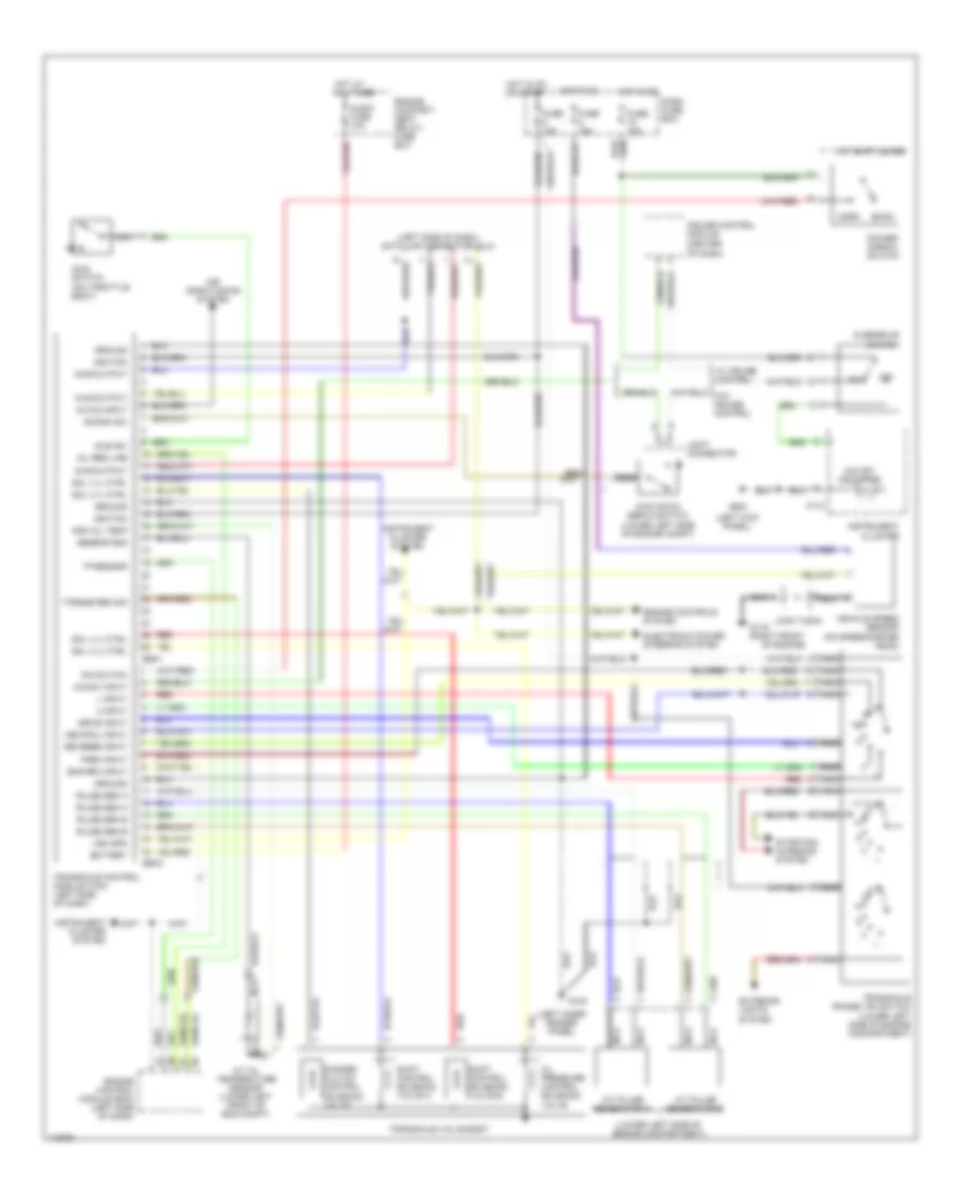
TRANSMISSION
A/T Wiring Diagram for Hyundai Tiburon FX 1997
List of elements for A/T Wiring Diagram for Hyundai Tiburon FX 1997:
- a/t pulse generator a
- a/t pulse generator b
- (center of dash)
- (left inner fender panel)
- (left kick panel)
- (left side of dash) data link connector (dlc)
- (lower left side of engine compartment)
- 101-2
- 2 input
- A/c on input
- A/t shift lever
- Air conditioning system
- Audio fuse 10a
- Battery
- Cruise control module
- Damper clutch control solenoid valve
- Dash fuse box
- Diag output
- Drive input
- E59-1
- E59-2
- Econ
- Electronic power steering system
- Eng rpm input
- Engine compart- ment relay/ fuse box
- Engine control module (ecm) (left side of dash)
- Engine controls system
- Exterior lights system
- Fuse 10a
- Fuse 15a
- G100
- G119 (right front
- G200
- Ground
- High oil temp
- Hot at all times
- Hot in on
- Hot in on or start
- Idle sw
- Idle switch (on throttle body)
- Ignition
- Instrument cluster
- Instrument cluster system
- Joint conn
- Joint connector
- Kick down servo switch (lower left side of engine compt)
- Kickdn sw
- L input
- Mil req line
- Nca
- Nca a/t oil temperature sensor (lower left front of eng compt)
- Neutral input
- Norm
- O/d off indicator
- O/d sw input
- Of engine)
- Off
- Oil pressure control solenoid valve
- Overdrive switch
- P-n switch
- Park input
- Power/ normal switch
- Pulse gen a
- Pulse gen b
- Red
- Reverse input
- Sensor gnd
- Shift control solenoid valve a
- Shift control solenoid valve b
- Sol vlv ctrl
- Starting/ charging system
- Torque red sig
- Tp sensor
- Transaxle control module (tcm) (left side of dash)
- Transaxle range (tr) switch
- Transaxle valve body
- Veh spd
- Vehicle speed sensor (on speedometer head)
- W/ cruise control
 English