TRANSMISSION
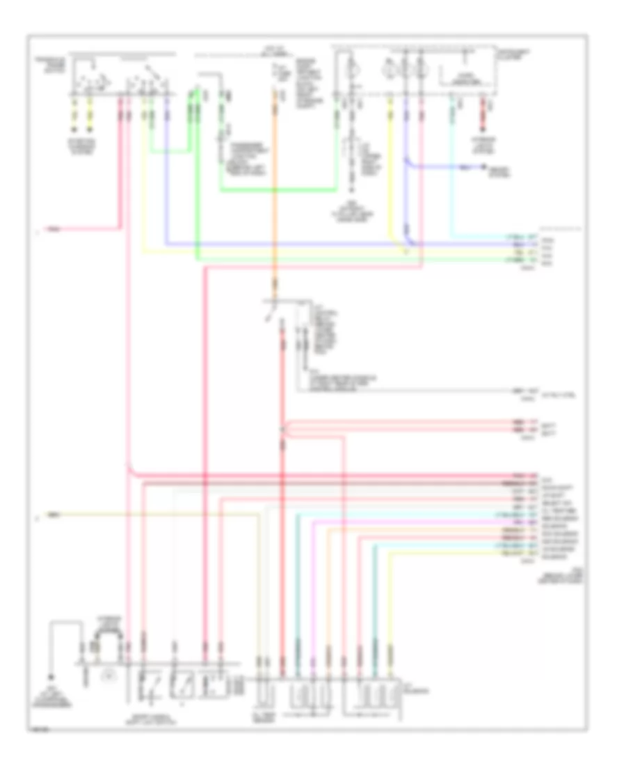
A/T Wiring Diagram (1 of 2) for Hyundai XG350 2004

List of elements for A/T Wiring Diagram (1 of 2) for Hyundai XG350 2004:
- (on top right side of transaxle) vehicle speed sensor
- A11
- Accelerator position sensor (on throttle body)
- Anti lock brakes system
- Aps sig
- Body computer, electronic power steering, instrument cluster systems
- C02
- C11
- C44-1
- C44-2
- C44-3
- C44-4
- Data link connector (below left side of dash)
- Ecm fuse 10a
- Engine compartment junction block (on left front of engine compt)
- Engine coolant temperature sensor & sender (on rear of engine)
- Etc sen
- Ets control module (behind center of dash, on support bracket)
- Exterior lights system
- Flash (eci)
- Fuse 10a
- Fuse 15a
- G04 (under center of dash, on center support bracket)
- G11 (on fire- wall, near throttle housing)
- G13 (under center console, right of srs control module)
- G14 (under center console, at right rear of srs control module)
- Ground
- Hot at all times
- Hot in on or start
- I/p-b
- I/p-e
- I/p-h
- Idle sw
- Ignition coil fuse 20a
- Immobilizer
- Immobilizer control module (left center of dash)
- Input speed
- J/c c42 (lower left center of dash)
- Jc01
- Jm09
- K-line
- Memory pwr
- Multipurpose check connector (at lower left side of dash)
- On/start in
- Output speed
- Passenger compartment junction block (behind left end of dash)
- Pcm (behind lower center of dash)
- Pnk
- Pulse generator a (on top of transaxle)
- Pulse generator b (on transaxle)
- Sens +5v
- Sens gnd
- Sens pwr
- Sensor
- Spark
- Stop lamp switch (above brake pedal, on bracket)
- Stop sw in
- Throttle position sensor (on left side of throttle body)
- Tps
- Tps sig
- Vss in
- W/o
A/T Wiring Diagram (2 of 2) for Hyundai XG350 2004
List of elements for A/T Wiring Diagram (2 of 2) for Hyundai XG350 2004:
- (behind left end of dash)
- 2nd solenoid
- A/t control relay (behind lower center of dash, behind pcm)
- A/t fuse 20a
- A/t rly ctrl
- A/t solenoid
- Batt
- C44-2
- C44-3
- C44-4
- D-in
- Dcc solenoid
- Down shift
- Engine comp- artment junction block (on left front of engine compt)
- G05 (on right "a" pillar, near crash bar)
- G07 (at left floorpanel crossmember)
- G14 (under center console, at right rear of srs control module)
- Ground
- Hot at all times
- I/p-h
- I18-1
- I18-2
- I18-3
- Instrument cluster
- Interior lights system
- J/c i28 (upper right side of dash)
- Jc01
- Jm09
- Memory system
- Micro computer
- N-in
- Normal
- Oil temp sen
- Oil temp sensor
- P-in
- Passenger compartment junction block i/p-k
- Pcm (behind lower center of dash)
- Pnk
- Pwm
- R-in
- Red
- Red solenoid
- Select
- Select sw
- Select switch
- Solenoid
- Sport mode & shift limit switch
- Starting/ charging system
- Transaxle range switch
- Ud solenoid
- Up shift