TRANSMISSION
A/T Wiring Diagram, Coupe for Infiniti G35 2007

List of elements for A/T Wiring Diagram, Coupe for Infiniti G35 2007:
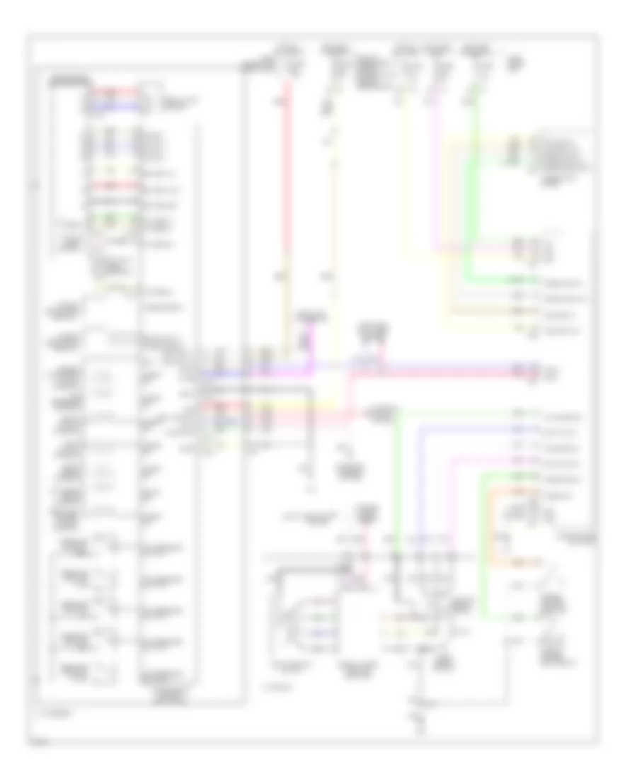
A/T Wiring Diagram, Sedan for Infiniti G35 2007
List of elements for A/T Wiring Diagram, Sedan for Infiniti G35 2007:
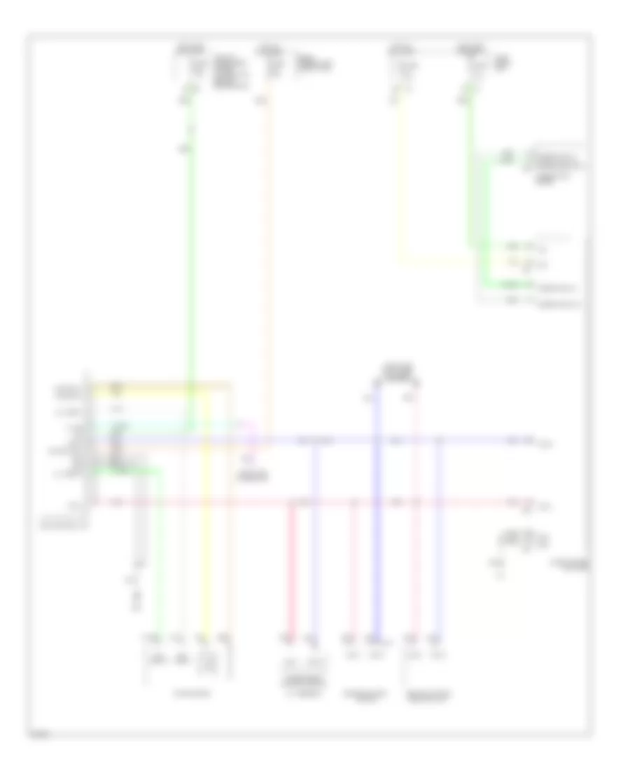
AWD Wiring Diagram, Sedan for Infiniti G35 2007
List of elements for AWD Wiring Diagram, Sedan for Infiniti G35 2007: