TRANSMISSION
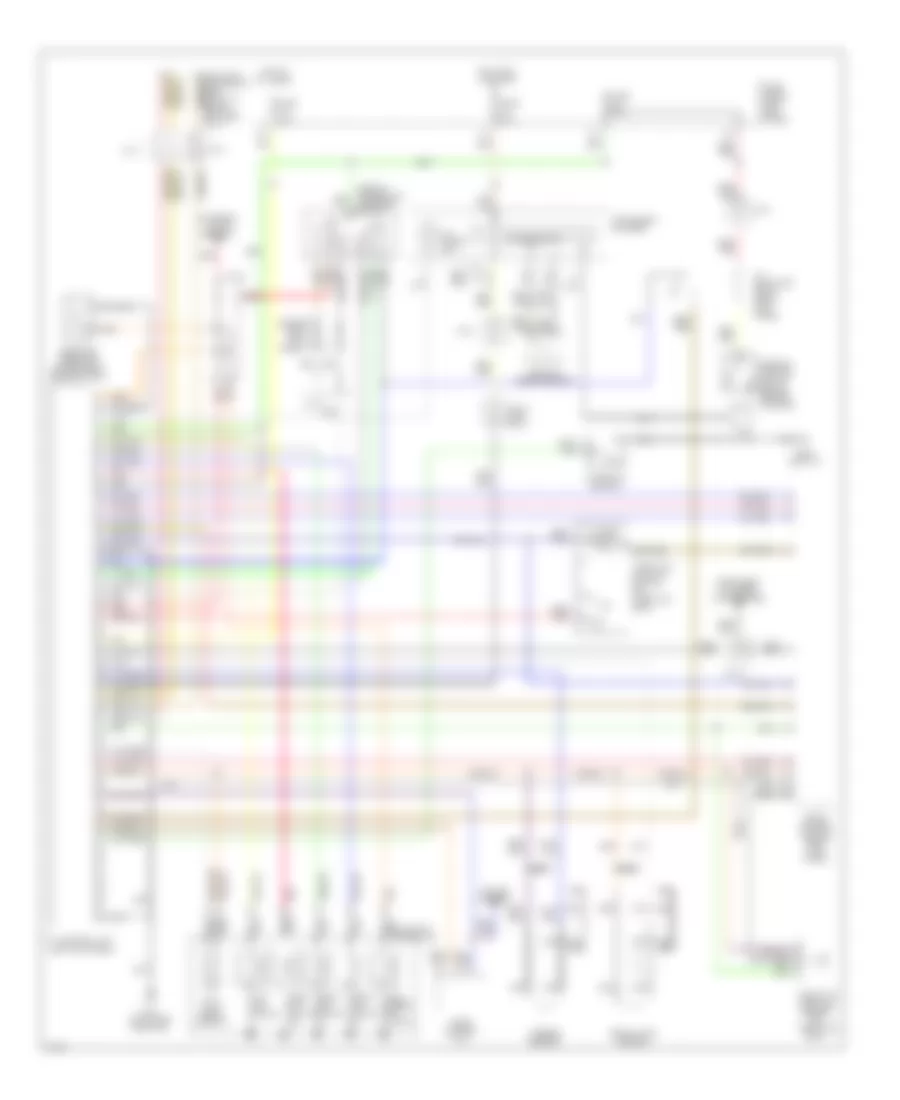
Transmission Wiring Diagram for Infiniti J30 1994
List of elements for Transmission Wiring Diagram for Infiniti J30 1994:
- (left kick panel)
- (side of transaxle) inhibitor switch
- 1-2
- A/t check ind.
- A/t control unit
- A/t fluid temp. sensor
- A/t indicator relay (right kick panel)
- All times
- Ascd control unit
- Automatic transaxle
- Closed throttle
- Cruise control
- Data link connector (for consult) (below left side of i/p)
- Diodes (left kick panel)
- Dropping resistor (on bracket, near battery)
- Eccs control module (right kick panel)
- Exterior lights (backup)
- Fuse 7.5a
- Fuse block (left kick panel)
- G131 (on intake manifold)
- G200 (left i/p)
- Hot at
- Hot in on or start
- Instrument cluster
- Instrument cluster (tachometer)
- J/c-10
- J/c-11
- J/c-12
- J/c-12 (1994 only)
- J/c-6
- J/c-8
- J/c-9
- Kickdown switch
- Line press. sol. valve
- Nca
- Over- run clutch sol.
- Parking position switch (below center console)
- Pnk
- Red
- Revolution sensor
- Shift sol. valve a
- Shift sol. valve b
- Speed sensor
- Speedometer
- Tcc sol. valve
- Throttle position sensor (on throttle body)
- Throttle position switch (on throttle body)
- Turbine sensor
- Vehicle
- Wot
 English