TRANSMISSION
4WD Wiring Diagram for Infiniti QX80 2014

List of elements for 4WD Wiring Diagram for Infiniti QX80 2014:
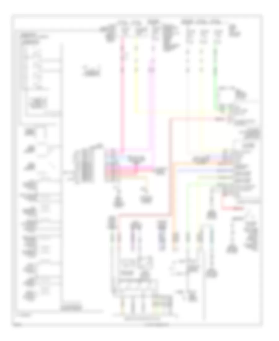
A/T Wiring Diagram for Infiniti QX80 2014
List of elements for A/T Wiring Diagram for Infiniti QX80 2014:
 English
4WD Wiring Diagram for Infiniti QX80 2014
List of elements for 4WD Wiring Diagram for Infiniti QX80 2014:
A/T Wiring Diagram for Infiniti QX80 2014
List of elements for A/T Wiring Diagram for Infiniti QX80 2014: