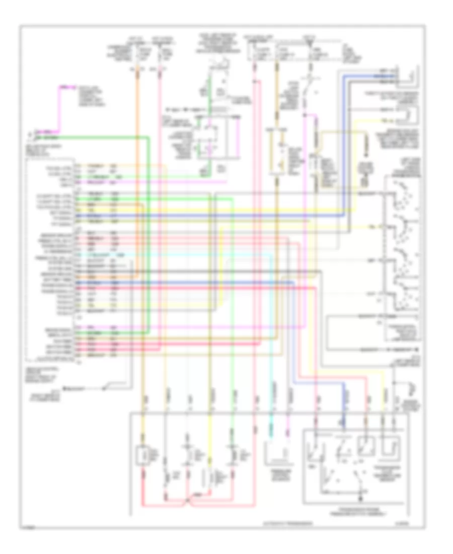
TRANSMISSION
2.2L
2.2L, A/T Wiring Diagram for Isuzu Hombre S 1998

List of elements for 2.2L, A/T Wiring Diagram for Isuzu Hombre S 1998:
- (twisted wire pair)
- (under left side of dash) data link connector (partial)
- 1-2 shift sol
- 1-2 ss vlv ctrl
- 2-3 shift sol
- 2-3 ss vlv ctrl
- 3-2 shift sol
- 3-2 ss vlv ctrl
- A10
- Abs fuse 22 10a
- Anti-lock brakes system
- Automatic transmission (4l60-e)
- Automatic transmission fluid pressure manual valve position switch
- Automatic transmission fluid temperature sensor
- Batt
- Brake sw in
- Class ii serial
- Clstr fuse 11 10a
- Ecm b fuse 20a
- Ecm i fuse 15a
- Ect sens gnd
- Ect sens sig
- Engine coolant temperature sensor (in coolant piping, on front of eng)
- G117 (right rear of eng block)
- G119 (right front of eng block, under generator)
- Gnd
- Hot at all times
- Hot in off, run or start
- Hot in run
- Hot in run or start
- I/p fuse block
- Ign 1
- Ign g wake up
- Nca
- Park/nuetral position & back up lamp switch
- Pc sol vlv ctrl hi
- Pc sol vlv ctrl lo
- Pcm ground 1
- Pcm ground 2
- Pcm ground 4
- Pnk
- Powertrain control module (on right front engine compt)
- Pressure control sol
- Red
- Rev
- Splice pack sp201 (left side of dash below fuse block)
- Stop lamp switch (on brake pedal support)
- Tan
- Tcc pwm sol
- Tcc pwm vlv ctrl
- Tcc sol
- Tcc sol vlv ctrl
- Tft sens gnd
- Tft sens sig
- Throttle position sensor (on throttle body)
- Tp sens 5v ref
- Tp sens gnd
- Tp sens sig
- Tr sw-a in
- Tr sw-b in
- Tr sw-c in
- Tr sw-p in
- Trans range-a
- Trans range-b
- Trans range-c
- Trans- mission range switch (left side of trans- mission)
- Underhood bussed electrical center
- Vehicle speed sensor (right rear of transmission,
- Vss hi
- Vss lo
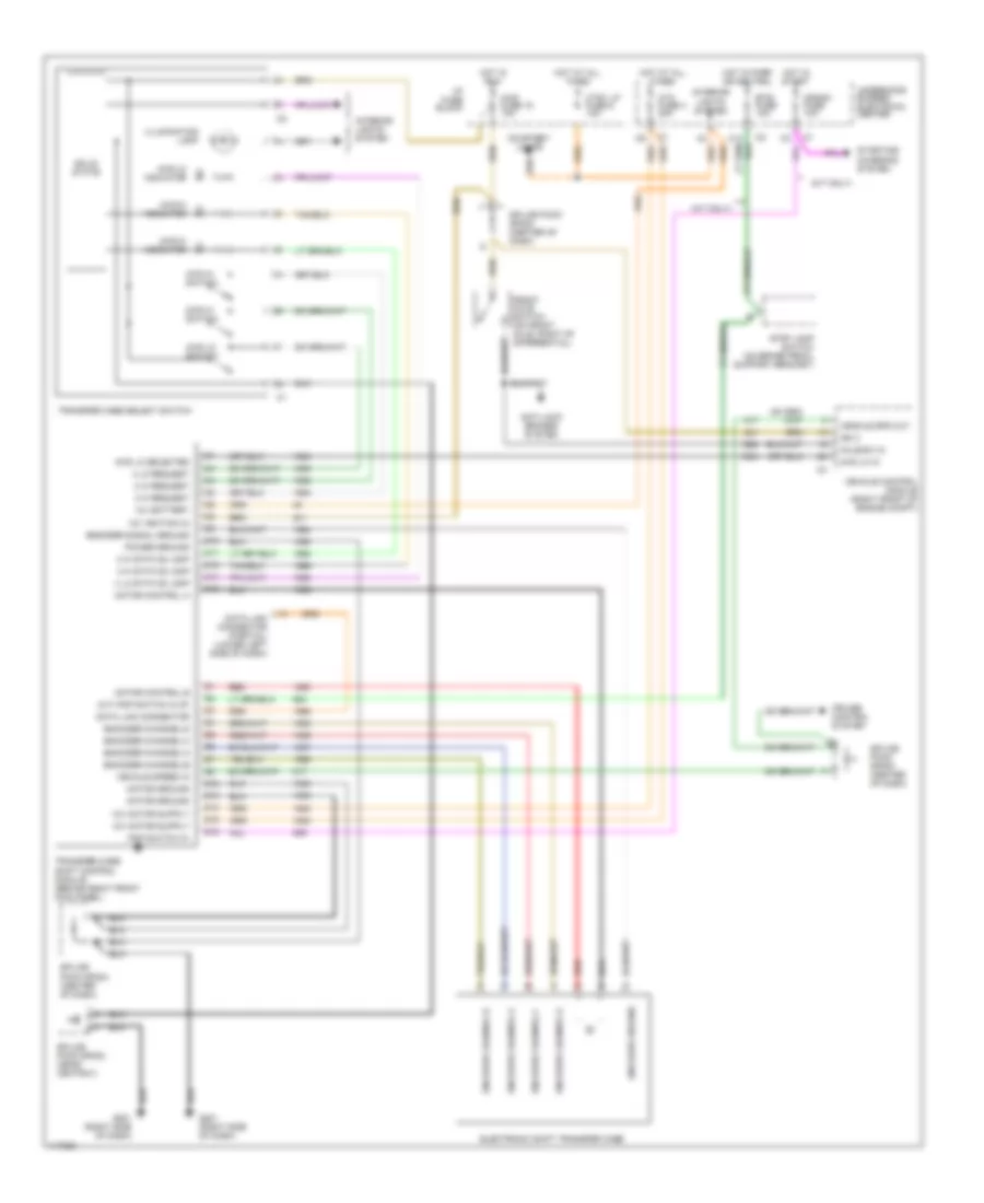
4WD Wiring Diagram for Isuzu Hombre S 1998
List of elements for 4WD Wiring Diagram for Isuzu Hombre S 1998:
- (a/t only)
- (a/t) pnp switch in (p)
- (m/t only)
- 12v battery
- 12v ignition (3)
- 2 hi request
- 2 hi status lamp
- 2wd hi indicator
- 2wd hi switch
- 4 hi request
- 4 hi status lamp
- 4 lo request
- 4 lo status lamp
- 4wd fuse 15 10a
- 4wd hi indicator
- 4wd hi switch
- 4wd lo in
- 4wd lo indicator
- 4wd lo selected
- 4wd lo switch
- Anti-lock brakes system
- Atc fuse 3 20a
- Axle sw in
- Btsi fuse 10a
- C10
- C11
- C12
- C14
- C16
- Courtesy lamps
- Crank fuse 10a
- Cruise control system
- Ctsy lp fuse 8 10a
- D12
- D13
- D14
- D15
- D16
- Data link connector
- Data link connector (partial) (lower left side of dash)
- Electronic shift transfer case
- Encoder channel a
- Encoder channel b
- Encoder channel c
- Encoder channel d
- Encoder channel-a
- Encoder channel-b
- Encoder channel-c
- Encoder channel-d
- Encoder ground
- Encoder signal ground
- Front axle switch (on front axle, right of differential)
- G201 (right side of dash)
- Hot at all times
- Hot in park or neutral
- Hot in run
- Hot in start
- I/p fuse block
- Ign 3
- Illumination lamp
- Interior lights system
- Motor control a
- Motor control b
- Motor ground
- Pnp switch in
- Power ground
- Red
- Solid state
- Splice pack sp200 (center of dash)
- Splice pack sp203 (near ashtray)
- Splice pack sp204 (center of dash)
- Starting/ charging system
- Stop lamp switch (on brake pedal support bracket)
- Transfer case select switch
- Transfer case shift control module (behind right front kick panel)
- Underhood bussed electrical center
- Vehicle control module (right front of engine compt)
- Vehicle spd out
- Vehicle speed in
4.3L
4.3L, A/T Wiring Diagram for Isuzu Hombre S 1998
List of elements for 4.3L, A/T Wiring Diagram for Isuzu Hombre S 1998:
- (4l60-e)
- (4wd: left rear of transfer case, (2wd: right rear of transmission) vehicle speed sensor
- (left side of trans- mission) transmission range switch
- (twisted wire pair)
- 1-2 shift sol
- 1-2 shift sol ctrl
- 2-3 shift sol
- 2-3 shift sol ctrl
- 2wd
- 3-2 shift sol
- 3-2 sol ctrl
- 4wd
- 5v reference
- Abs
- All times
- Automatic transmission
- B10
- Battery feed
- Body relay block (behind left side of dash)
- Brake signal
- Clstr
- Clutch cpp sw in
- Cruise control module
- Data link connector (partial) (under left side of dash)
- Ecm b
- Ecm i fuse 15a
- Ect signal
- Engine controls system
- Engine coolant temperature sensor (left cylinder head, between left two rear spark plugs)
- Fuse 11 10a
- Fuse 15 10a
- Fuse 20a
- Fuse 22 10a
- G114 (left rear of cylinder head)
- G117 (right rear of cylinder head)
- Gnd
- Hot at
- Hot in run
- Hot in run, off or start
- I/p fuse block (left end of dash)
- Ignition feed
- Junction connector c116 (near top rear of trans- mission)
- Nca
- Or start
- Park/nuetral position & back up lamp switch
- Pnk
- Press ctrl so hi
- Press ctrl sol lo
- Pressure control solenoid
- Range signal-a
- Range signal-b
- Range signal-c
- Red
- Rev
- Run feed
- Sensor ground
- Serial data
- Splice pack sp200 (center front of dash)
- Splice pack sp201 (below i/p fuse block)
- System gnd
- Tan
- Tcc pwm sol
- Tcc pwm sol ctrl
- Tcc sol
- Tcc sol ctrl
- Tft signal
- Throttle position sensor (on throttle body assembly)
- Tp signal
- Tr sw-a
- Tr sw-b
- Tr sw-c
- Tr sw-p
- Transmission fluid temperature sensor
- Transmission range pressure switch assembly
- Underhood bussed electrical center
- Vehicle control module (right front of engine compt)
- Vss hi
- Vss lo
4WD Wiring Diagram for Isuzu Hombre S 1998
List of elements for 4WD Wiring Diagram for Isuzu Hombre S 1998:
- (a/t only)
- (a/t) pnp switch in (p)
- (m/t only)
- 12v battery
- 12v ignition (3)
- 2 hi request
- 2 hi status lamp
- 2wd hi indicator
- 2wd hi switch
- 4 hi request
- 4 hi status lamp
- 4 lo request
- 4 lo status lamp
- 4wd fuse 15 10a
- 4wd hi indicator
- 4wd hi switch
- 4wd lo in
- 4wd lo indicator
- 4wd lo selected
- 4wd lo switch
- Anti-lock brakes system
- Atc fuse 3 20a
- Axle sw in
- Btsi fuse 10a
- C10
- C11
- C12
- C14
- C16
- Courtesy lamps
- Crank fuse 10a
- Cruise control system
- Ctsy lp fuse 8 10a
- D12
- D13
- D14
- D15
- D16
- Data link connector
- Data link connector (partial) (lower left side of dash)
- Electronic shift transfer case
- Encoder channel a
- Encoder channel b
- Encoder channel c
- Encoder channel d
- Encoder channel-a
- Encoder channel-b
- Encoder channel-c
- Encoder channel-d
- Encoder ground
- Encoder signal ground
- Front axle switch (on front axle, right of differential)
- G201 (right side of dash)
- Hot at all times
- Hot in park or neutral
- Hot in run
- Hot in start
- I/p fuse block
- Ign 3
- Illumination lamp
- Interior lights system
- Motor control a
- Motor control b
- Motor ground
- Pnp switch in
- Power ground
- Red
- Solid state
- Splice pack sp200 (center of dash)
- Splice pack sp203 (near ashtray)
- Splice pack sp204 (center of dash)
- Starting/ charging system
- Stop lamp switch (on brake pedal support bracket)
- Transfer case select switch
- Transfer case shift control module (behind right front kick panel)
- Underhood bussed electrical center
- Vehicle control module (right front of engine compt)
- Vehicle spd out
- Vehicle speed in