TRANSMISSION
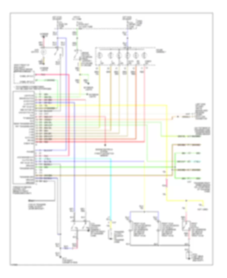
4WD Wiring Diagram, Shift on the Fly for Isuzu Trooper LS 1998

List of elements for 4WD Wiring Diagram, Shift on the Fly for Isuzu Trooper LS 1998:
- (under side of vehicle, center of front axle)
- 4wd control unit (behind front console)
- 4wd engaged out
- 4wd ind
- 4wd ind ctrl
- 4wd motor actuator (on rear of transfer case)
- 4wd mtr ctrl
- 4wd switch
- 4wd switch (on top right of transfer case)
- Anti-lock brakes system
- C-1 meter gauge fuse 10a
- C-4 elec. ig. fuse 15a
- Dash fuse box
- Front axle switch (under side of vehicle, center of front axle)
- Front axle vacuum solenoid valve (c) (gray)
- Frt axle engaged
- Frt axle vsv
- G104 (left rear corner of eng compt)
- Gnd
- High/4l in
- Hot in on or start
- I-9
- Ign
- Illum
- Interior lights system
- M-11
- M-12
- Meter assembly
- Off
- On/off in
- Pnk
- Red
- Trans complete
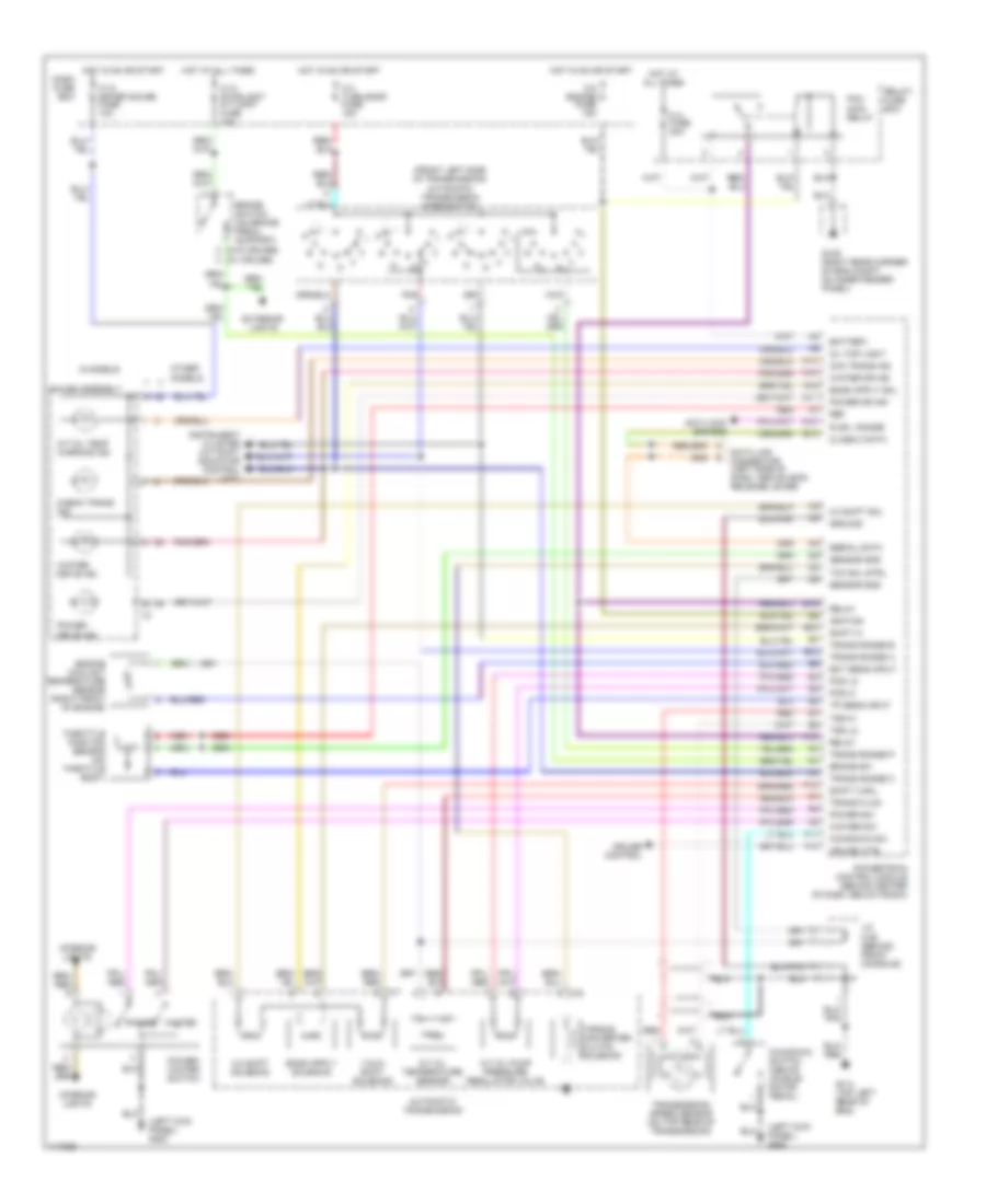
4WD Wiring Diagram, Torque on Demand for Isuzu Trooper LS 1998
List of elements for 4WD Wiring Diagram, Torque on Demand for Isuzu Trooper LS 1998:
- (1)
- (10)
- (11)
- (12)
- (13)
- (14)
- (15)
- (16)
- (17)
- (18)
- (19)
- (2)
- (20)
- (21)
- (22)
- (23)
- (24)
- (25)
- (26)
- (27)
- (28)
- (29)
- (3)
- (30)
- (4)
- (5)
- (6)
- (7)
- (8)
- (9)
- (left side of dash, above engine hood release lever) data link connector
- (not used)
- (on top rear of transfer case) transfer rear speed sensor
- (right front of eng compt) electronic brake control module
- (top of transfer case, on shift lever bracket)
- (w/o cruise) (w/ cruise)
- 1 ind
- 2 ind
- 3 ind
- 4 h/l transfer switch assembly (bottom front of transfer case)
- 4h switch
- 4l switch
- 4wd engage out
- 4wd switch
- 4wd switch on
- Abs actice in
- Auto ind
- Brake switch
- Brake switch (on brake pedal support)
- C-10 meter fuse 10a
- C-14 stoplight a/t cont fuse 15a
- C-4 elec ign fuse 15a
- Check ind
- Clutch sol
- Dash fuse box
- Dlc
- Engine controls system (throttle position sensor)
- Exterior lights
- Front axle switch (on underside of vehicle, center of front axle)
- Front axle vacuum solenoid valve (gray) (on underside of vehicle, center of front axle)
- Frt axle in
- Frt axle vsv
- Frt transfer spd
- G104 (left rear corner of eng compt)
- G117 (top right corner of eng)
- Gauge assembly
- Ground
- Hot at all times
- Hot in on or start
- I-9
- Ind
- Interior lights
- Lights on
- M-27
- May be used for testing purposes
- Pin numbers in parenthesis
- Pnk
- Power
- Rear transfer spd
- Red
- Rr ind
- Torque on demand control unit (beneath front passenger's seat)
- Tp sensor
- Transfer clutch solenoid (in transfer case)
- Transfer front speed sensor (on lower rear of transfer case)
- Transfer spd
- Wheel sp out
A/T Wiring Diagram for Isuzu Trooper LS 1998
List of elements for A/T Wiring Diagram for Isuzu Trooper LS 1998:
- (front left side of transmission) automatic transmission mode switch
- (left kick panel) g200
- (w/o cruise) (w/ cruise)
- 1-2/3-4 shift solenoid
- 2-3 shift sol
- 2-3 shift solenoid
- A/t oil pump pressure regulator valve
- A/t oil temp warning ind
- A/t oil temperature sensor
- A16
- Anti-lock brakes
- Automatic transmission
- B13
- Battery
- Brake sw
- Brake switch (on brake pedal support)
- C-10 meter gauge fuse 10a
- C-14 stoplight a/t cont fuse 15a
- C-3 turn back fuse 15a
- C-8 engine fuse 15a
- Check trans ind
- Chk trans ind
- Class 2 data
- Cruise control
- Cruise ctrl
- Dash fuse box
- Data link connector (left side of dash, above hood release lever)
- E12
- E14
- Ect sens input
- Engine coolant temperature sensor (right front of engine)
- Exterior lights
- F10
- F11
- F14
- Fl3 fuse 30a
- G105 (right rear corner of eng compt, on inner fender panel)
- G114 (top left rear of eng)
- Gauge assembly
- Ground
- Hot at all times
- Hot in on or start
- I-9
- Ignition
- Instrument cluster (a/t shift indicator control unit)
- Interior lights
- J/c c-88 (behind front console)
- Kickdown sw
- Kickdown switch (above accele- rator pedal)
- M-6
- M-7
- Oil tmp light
- Other models
- Pcm main relay
- Pcs hi
- Pcs lo
- Pnk
- Power
- Power dr ind
- Power drive ind
- Power sw
- Power/ winter switch
- Powertrain control module (behind center of dash, below radio)
- R or l range
- Red
- Ref
- Relay
- Relay/ fuse box
- S models
- Sensor gnd
- Serial data
- Shift a sol
- Shift hi
- Tcc sol strl
- Throttle position sensor (on throttle body)
- Torque converter clutch solenoid
- Tp sens input
- Trans fluid
- Trans range a
- Trans range b
- Trans range c
- Trans range p
- Transmission speed sensor (on top rear of transmission)
- Tss hi
- Tss lo
- Winter
- Winter dr ind
- Winter drive ind
- Winter sw