AUTOMOTIVE ELECTRICIANS PORTAL

TRANSMISSION – Land Rover Range Rover 2013 – SYSTEM WIRING DIAGRAMS

TRANSMISSION

4WD Wiring Diagram for Land Rover Range Rover 2013

4WD Wiring Diagram for Land Rover Range Rover 2013 https://portal-diagnostov.com/license.html
https://portal-diagnostov.com/license.html Automotive Electricians Portal FZCO Automotive Electricians Portal FZCO
Download PDF file

List of elements for 4WD Wiring Diagram for Land Rover Range Rover 2013:

  • C13-b1
  • C13-b2
  • C1bb01b
  • C2bp01c
  • C2mc01a
  • C31-a1
  • C31-a2
  • C32-m1
  • C32-m2
  • C32-o1
  • C32-o2
  • C32-x1
  • C32-x2
  • C3et73a
  • C3et73b
  • C3et73c
  • Central junction box (behind left side of dash)
  • Computer data lines system
  • Engine junction box (right rear corner of engine compt)
  • Fuse 5a
  • Fusible link 8 30a
  • G3d383b (under front of passenger seat)
  • Gnd
  • Hall gnd
  • Hall ina
  • Hall inb
  • Hall pwr
  • Hall sensor a
  • Hall sensor b
  • Hall v+
  • Hot at all times
  • Hot w/ ignition relay energized
  • Hs can h
  • Hs can l
  • Ign
  • Instrument cluster
  • Low range high position sensor
  • Low range high solenoid
  • Motor pos
  • Motor+
  • Motor-
  • Pwr
  • Range sw
  • Sensor gnd
  • Sensor sig
  • Sig
  • Snsr pwr
  • Solenoid +
  • Solenoid -
  • Sw hi/lo ratio
  • Temp
  • Terrain response switch pack
  • Transfer case control module (left rear of engine compt)
  • Transfer case motor
  • Vbatt1

A/T Wiring Diagram for Land Rover Range Rover 2013

AT Wiring Diagram for Land Rover Range Rover 2013 https://portal-diagnostov.com/license.html
https://portal-diagnostov.com/license.html Automotive Electricians Portal FZCO Automotive Electricians Portal FZCO
모든 배선 다이어그램에 액세스하십시오.Download PDF file

List of elements for A/T Wiring Diagram for Land Rover Range Rover 2013:
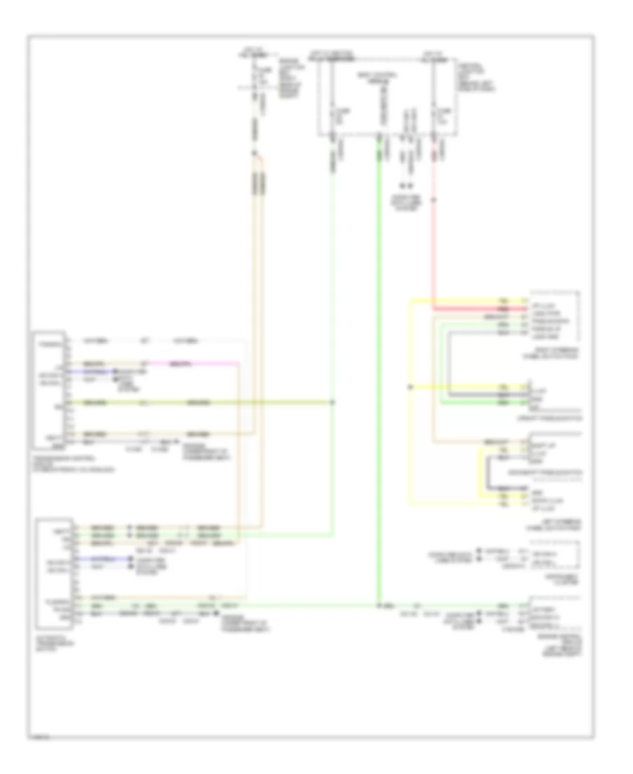
  • Automatic transmission switch
  • B-d-can h1
  • B-d-can l1
  • Body control module
  • C13-b1
  • C13-b2
  • C1bb01b
  • C1e120b
  • C2bp01e
  • C2bp01g
  • C2mc01a
  • C31-a1
  • C31-a2
  • C32-m1
  • C32-m2
  • C32-o1
  • C32-o2
  • C32-x1
  • C32-x2
  • C3bp01c
  • Central junction box (behind left side of dash)
  • Computer data lines system
  • Down illum
  • Downshift paddle switch
  • Engine control module (left rear of engine compt)
  • Engine junction box (right rear of engine compt)
  • Fuse 10a
  • Fuse 15a
  • Fuse 5a
  • G3d383b (under front of passenger seat)
  • Gnd
  • Hot at all times
  • Hot w/ ignition relay energized
  • Hs can h
  • Hs can l
  • I-s-tnsw
  • Ign
  • Illum
  • Instrument cluster
  • Left steering wheel switch pack
  • Lin
  • Logic gnd
  • Logic pwr
  • P-signal
  • Paddle down
  • Paddle up
  • Park neut sig
  • Pn sig
  • P_signal
  • Red
  • Right steering wheel switch pack
  • Shift up
  • Transmission control module (in mechatronic valve block)
  • Up illum
  • Upshift paddle switch
  • Vbatt

Rear Differential Lock Wiring Diagram for Land Rover Range Rover 2013

Rear Differential Lock Wiring Diagram for Land Rover Range Rover 2013 https://portal-diagnostov.com/license.html
https://portal-diagnostov.com/license.html Automotive Electricians Portal FZCO Automotive Electricians Portal FZCO
모든 배선 다이어그램에 액세스하십시오.Download PDF file

List of elements for Rear Differential Lock Wiring Diagram for Land Rover Range Rover 2013:
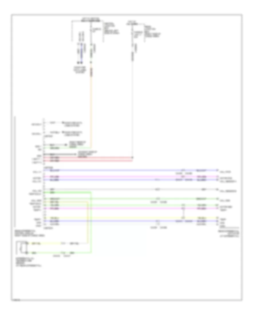
  • (on right side of cargo area) g4d150d
  • (right rear of cargo area) g4d351
  • C2bp01c
  • C2bp01e
  • C44-b1
  • C44-b2
  • C44-c1
  • C44-c2
  • C4br02a
  • C4et63a
  • C4et63b
  • C4et63c
  • Central junction box (behind left side of dash)
  • Computer data lines system
  • Differential oil temperature sensor (at rear differential)
  • Fuse 22 5a
  • Fusible link 11 40a
  • Gnd
  • Gnd 1
  • Hall gnd
  • Hall in1
  • Hall in2
  • Hall pwr
  • Hall sensor a
  • Hall sensor b
  • Hall v+
  • Hot at all times
  • Hot w/ ignition relay energized
  • Hs can h
  • Hs can l
  • Ign
  • Mag+
  • Mag-
  • Motor -
  • Motor pos
  • Motor+
  • Rear differential actuator (at differential)
  • Rear differential control module (right side of cargo area)
  • Rear junction box (right side of cargo area)
  • Temp sig 2+
  • Temp sig 2-
  • Temp+
  • Temp-
  • Temp1+
  • Temp1-
  • V batt 1
  • V batt 2