AUTOMOTIVE ELECTRICIANS PORTAL

TRANSMISSION – Land Rover Range Rover HSE 2014 – SYSTEM WIRING DIAGRAMS

TRANSMISSION

A/T Wiring Diagram for Land Rover Range Rover HSE 2014

AT Wiring Diagram for Land Rover Range Rover HSE 2014 https://portal-diagnostov.com/license.html
https://portal-diagnostov.com/license.html Automotive Electricians Portal FZCO Automotive Electricians Portal FZCO
Download PDF file

List of elements for A/T Wiring Diagram for Land Rover Range Rover HSE 2014:

  • Automatic transmission switch (under center console)
  • B d can h1
  • B d can l1
  • Body control module
  • C13-b1
  • C13-b2
  • C1bb01b
  • C1e120b
  • C2bp01c
  • C2bp01e
  • C2bp01g
  • C2mc01a
  • C31-a1
  • C31-a2
  • C32-m1
  • C32-m2
  • C32-o1
  • C32-o2
  • C32-x1
  • C32-x2
  • Central junction box (right end of dash)
  • Computer data lines system
  • Crank request
  • Down
  • Down illum
  • Downshift paddle switch
  • Engine control module (left rear of engine compt)
  • Engine junction box (right rear corner of engine compt)
  • Fuse 10a
  • Fuse 15a
  • Fuse 5a
  • G3d383b (under front of passenger seat)
  • Gnd
  • Hot at all times
  • Hot w/ ignition relay energized
  • Hs can h
  • Hs can l
  • I s t50
  • I s tnsw
  • Ign
  • Illum
  • Instrument cluster
  • Left steering wheel switchpack
  • Logic gnd
  • Logic pwr
  • P-signal
  • Paddle down
  • Paddle up
  • Park neut sig
  • Pin sig
  • Red
  • Right steering wheel switchpack
  • Tcmp
  • Transmission control module (in mechatronic valve block)
  • Up illum
  • Upshift paddle switch
  • Vbatt

AWD Wiring Diagram for Land Rover Range Rover HSE 2014

AWD Wiring Diagram for Land Rover Range Rover HSE 2014 https://portal-diagnostov.com/license.html
https://portal-diagnostov.com/license.html Automotive Electricians Portal FZCO Automotive Electricians Portal FZCO
Get access to all wiring diagrams of the carDownload PDF file

List of elements for AWD Wiring Diagram for Land Rover Range Rover HSE 2014:
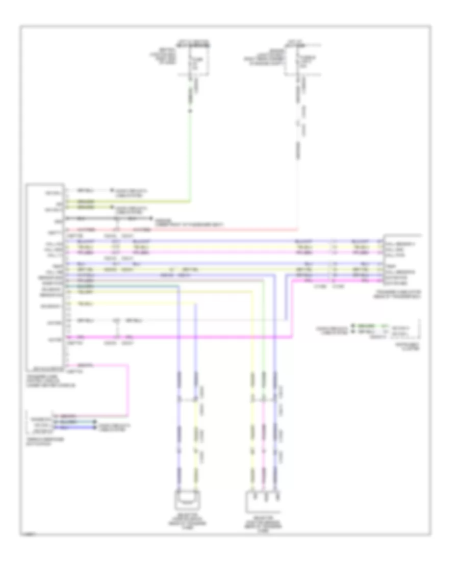
  • C13-b1
  • C13-b2
  • C1bb01b
  • C2bp01c
  • C2mc01a
  • C31-e1
  • C31-e2
  • C32-m1
  • C32-m2
  • C32-o1
  • C32-o2
  • C32-x1
  • C32-x2
  • C3et73a
  • C3et73b
  • C3et73c
  • Central junction box (right end of dash)
  • Computer data lines system
  • Engine junction box (right rear corner of engine compt)
  • Fuse 5a
  • Fusible link 8 30a
  • G3d383b (under front of passenger seat)
  • Gnd
  • Hall gnd
  • Hall ina
  • Hall inb
  • Hall pwr
  • Hall sensor a
  • Hall sensor b
  • Hall v+
  • Hot at all times
  • Hot w/ ignition relay energized
  • Hs can h
  • Hs can l
  • Ign
  • Instrument cluster
  • Motor pos
  • Motor+
  • Motor-
  • Pwr
  • Range sw
  • Selector mode solenoid (rear of transfer case)
  • Selector position sensor (rear of transfer case)
  • Sensor gnd
  • Sensor sig
  • Sig
  • Snsr pwr
  • Solenoid +
  • Solenoid -
  • Sw hi/lo ratio
  • Temp
  • Terrain response switchpack
  • Transfer case control module (under center console)
  • Transfer case motor (rear of transfer box)
  • Vbatt1

Rear Differential Lock Wiring Diagram for Land Rover Range Rover HSE 2014

Rear Differential Lock Wiring Diagram for Land Rover Range Rover HSE 2014 https://portal-diagnostov.com/license.html
https://portal-diagnostov.com/license.html Automotive Electricians Portal FZCO Automotive Electricians Portal FZCO
Get access to all wiring diagrams of the carDownload PDF file

List of elements for Rear Differential Lock Wiring Diagram for Land Rover Range Rover HSE 2014:
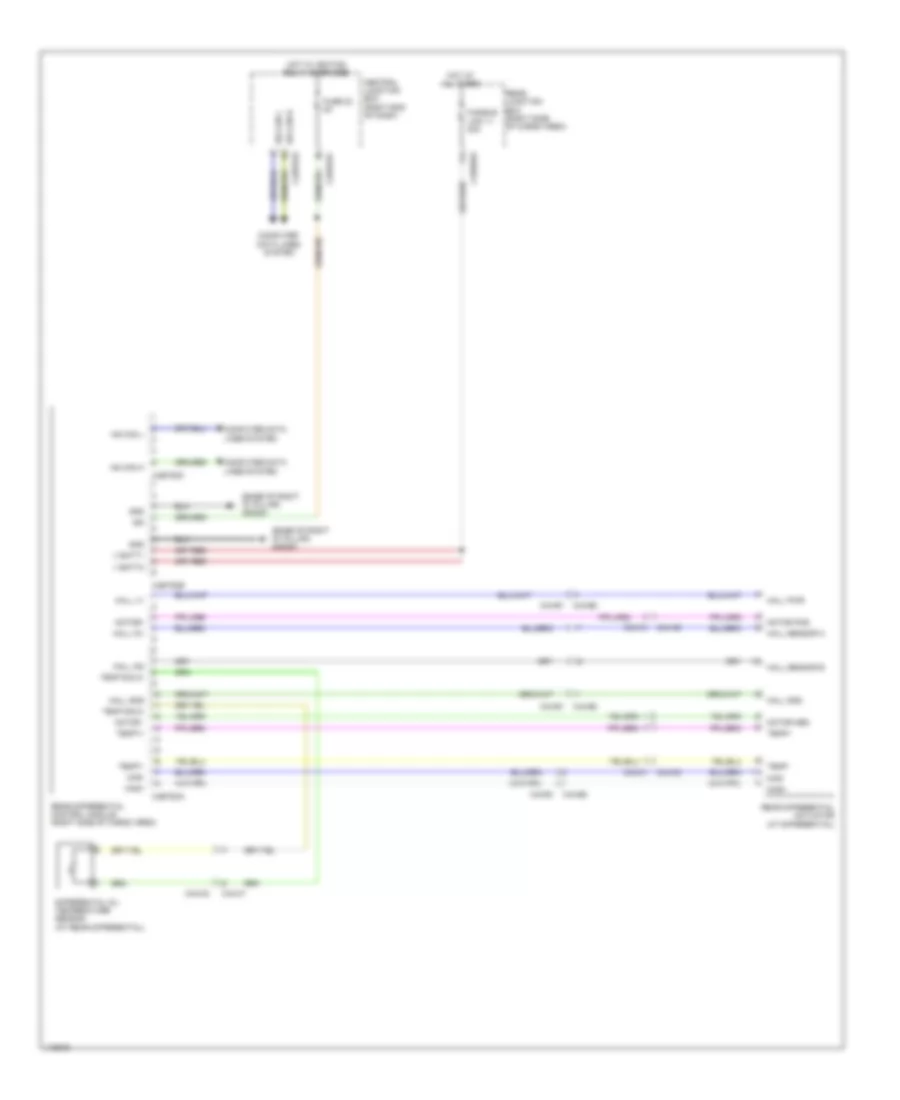
  • (base of right "d" pillar) g4d351
  • C2bp01c
  • C2bp01e
  • C44-b1
  • C44-b2
  • C44-c1
  • C44-c2
  • C4br02a
  • C4et63a
  • C4et63b
  • C4et63c
  • Central junction box (right end of dash)
  • Computer data lines system
  • Differential oil temperature sensor (at rear differential)
  • Fuse 22 5a
  • Fusible link 11 40a
  • Gnd
  • Hall gnd
  • Hall in1
  • Hall in2
  • Hall pwr
  • Hall sensor a
  • Hall sensor b
  • Hall v+
  • Hot at all times
  • Hot w/ ignition relay energized
  • Hs can h
  • Hs can l
  • Ign
  • Mag+
  • Mag-
  • Motor -
  • Motor pos
  • Motor+
  • Rear differential actuator (at differential)
  • Rear differential control module (right side of cargo area)
  • Rear junction box (right side of cargo area)
  • Temp sig 2+
  • Temp sig 2-
  • Temp+
  • Temp-
  • Temp1+
  • Temp1-
  • V batt1
  • V batt2