TRANSMISSION
A/T Wiring Diagram for Land Rover Range Rover Supercharged 2014

List of elements for A/T Wiring Diagram for Land Rover Range Rover Supercharged 2014:
AWD Wiring Diagram for Land Rover Range Rover Supercharged 2014
List of elements for AWD Wiring Diagram for Land Rover Range Rover Supercharged 2014:
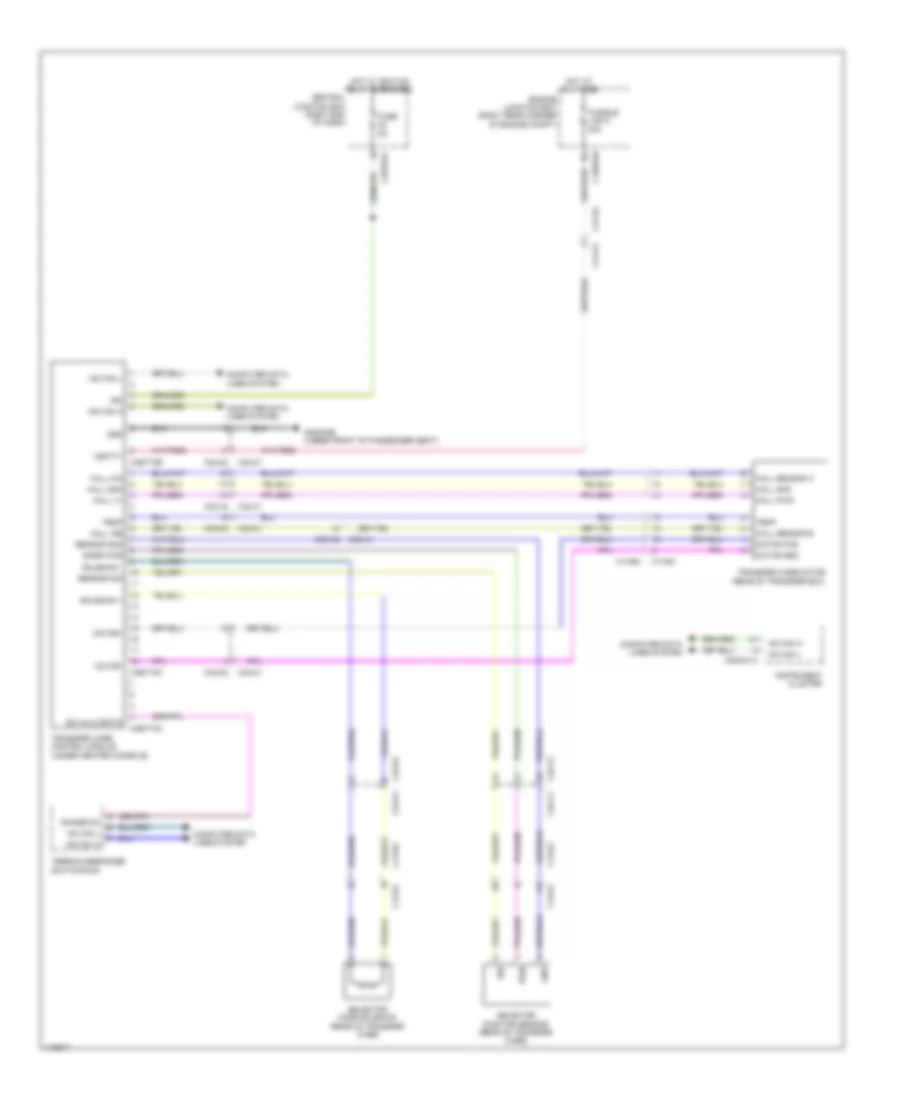
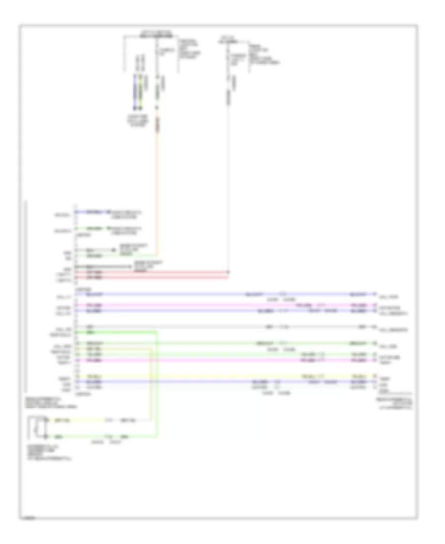
Rear Differential Lock Wiring Diagram for Land Rover Range Rover Supercharged 2014
List of elements for Rear Differential Lock Wiring Diagram for Land Rover Range Rover Supercharged 2014: