TRANSMISSION
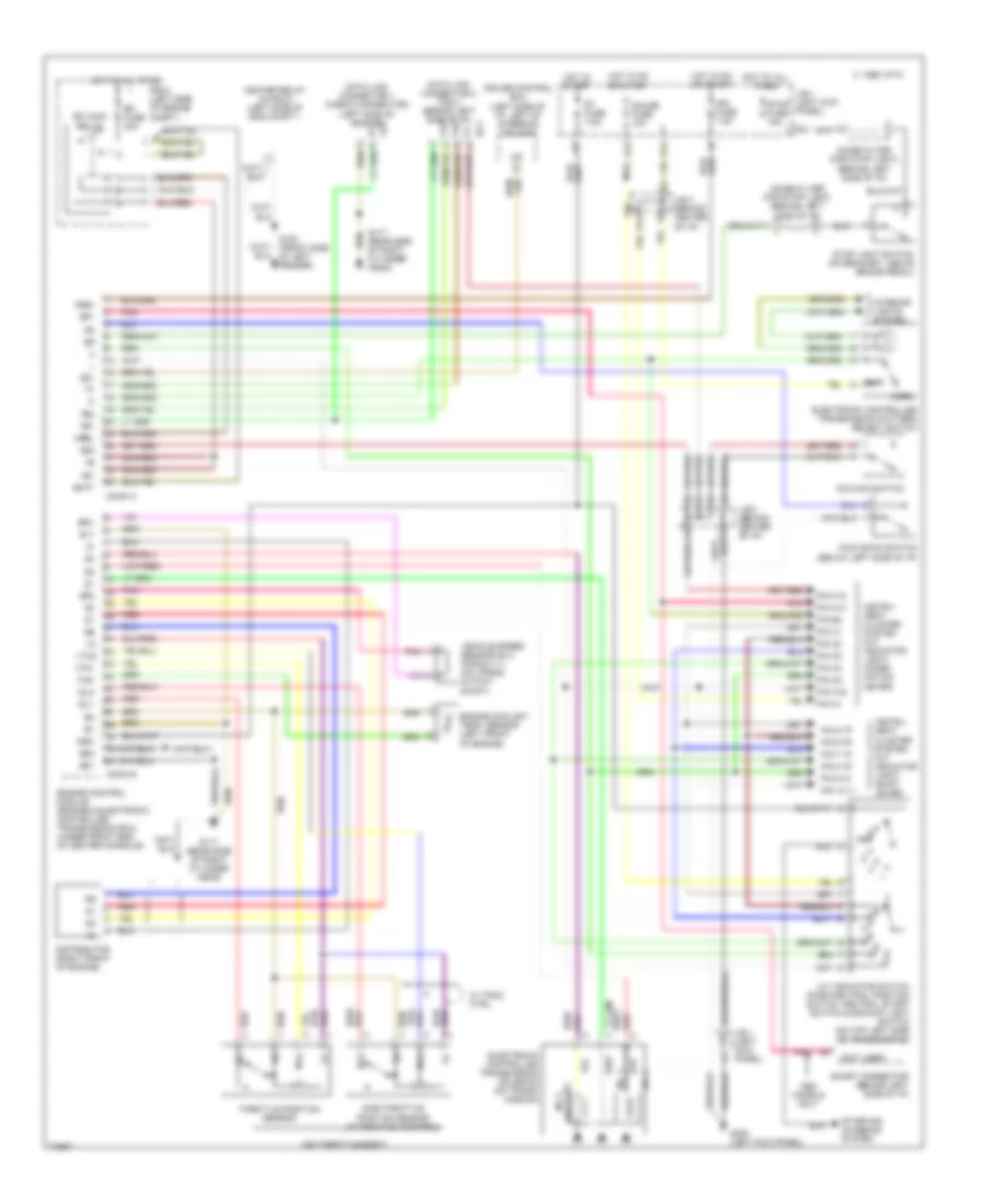
Transmission Wiring Diagram for Lexus SC 300 1993
List of elements for Transmission Wiring Diagram for Lexus SC 300 1993:
- (below left side of i/p)
- (lock-up) no.3
- (not used)
- (on throttle body)
- +b1
- A/t indicator switch (park/neutral position switch, neutral start switch & backup light switch (on top left side of transmission)
- Batt
- C 1995 vftc
- Conn a
- Conn b
- Cruise control ecu (left side of i/p, left of steering column)
- D13
- Data link connector 1 (check connector) (left side of engine)
- Data link connector 2 (tdcl) (behind left side of i/p)
- Distributor (right front of engine)
- E11
- E12
- E18
- Ect
- Efi fuse 30a
- Efi main relay
- Electronic controlled transmission pattern select switch
- Electronic controlled transmission solenoid (on trans- mission)
- Engine control module (engine & electronic controlled transmission ecu) (under front end of center console)
- Engine coolant temp. sensor (left front of engine)
- Eo1
- Eo2
- G100 (front side of left fender)
- G117 (rear side of right cylinder head)
- G200 (left kick panel)
- Gauge fuse 10a
- H12
- Heater relay (in r/b 2) (left side of eng compt.)
- Hot at all times
- Hot in on or start
- Hot in start
- I10
- Idl
- Idl1
- Idl2
- Ign fuse 7.5a
- Igsw
- Instru- ment cluster system (a/t indicator light) (combi- nation meter)
- Instru- ment cluster system (a/t indicator light) (shift lever)
- Interior lights system
- J/b 1 (left kick panel)
- J/b 3 (behind center of i/p)
- Kick down switch
- Models only
- Mrel
- No. 1
- No. 2
- Noise filter (for stop light) (behind left side of i/p)
- Norm.
- Nsw
- O/d main switch
- Od1
- Od2
- Pin 10 "l"
- Pin 5 "p"
- Pin 6 "r"
- Pin 7 "n"
- Pin 8 "d"
- Pin 9 "2"
- Pin a1
- Pin a14
- Pin b4
- Pin c1
- Pin c16
- Pin c18
- Pin c2
- Pin c3
- Pin c4
- Pin c5
- Pnk
- Pwr
- R n
- R/b 2 (left side of engine compt.)
- Red
- Short connector (behind left side of i/p)
- Sp1
- Sp2
- Sp2-
- St fuse 7.5a
- Starting/ charging system
- Stop fuse 15a
- Stop light switch (on bracket, above brake pedal)
- Sub-throttle position sensor (w/traction control)
- Te1
- Te2
- Throttle position sensor
- Thw
- Vehicle speed sensor no.2 (for e.c.t.) (on trans. output shaft)
- Vta
- Vta1
- Vta2
- W/ trac. ctrl.
 English