TRANSMISSION
A/T Wiring Diagram (1 of 2) for Mazda 3 i 2004

List of elements for A/T Wiring Diagram (1 of 2) for Mazda 3 i 2004:
- (at transaxle range switch)
- (behind left side of dash) brake switch
- 1aa
- 1ai
- 1am
- 1at
- 1au
- 1av
- 1ax
- 1ay
- 1az
- 1ba
- 1bb
- 1bd
- 1be
- 1bf
- 1bg
- 1bh
- Back fuse 10a
- Computer data lines system
- Control valve body
- Engine controls system
- Exterior lights system
- G16
- G5 (left front of engine compt)
- G6 (left rear of engine)
- Hot in run
- Input turbine speed sensor (on transaxle)
- J-01
- J-05
- Passenger junction box (behind right side of dash)
- Powertrain control module (rear of engine compt)
- Pressure control solenoid
- R position
- Red
- Shift sol a
- Shift sol b
- Shift sol c
- Shift sol d
- Shift sol e
- Transaxle fluid temp sensor
- Transaxle range switch (on transaxle)
- Vehicle speed sensor (on transaxle)
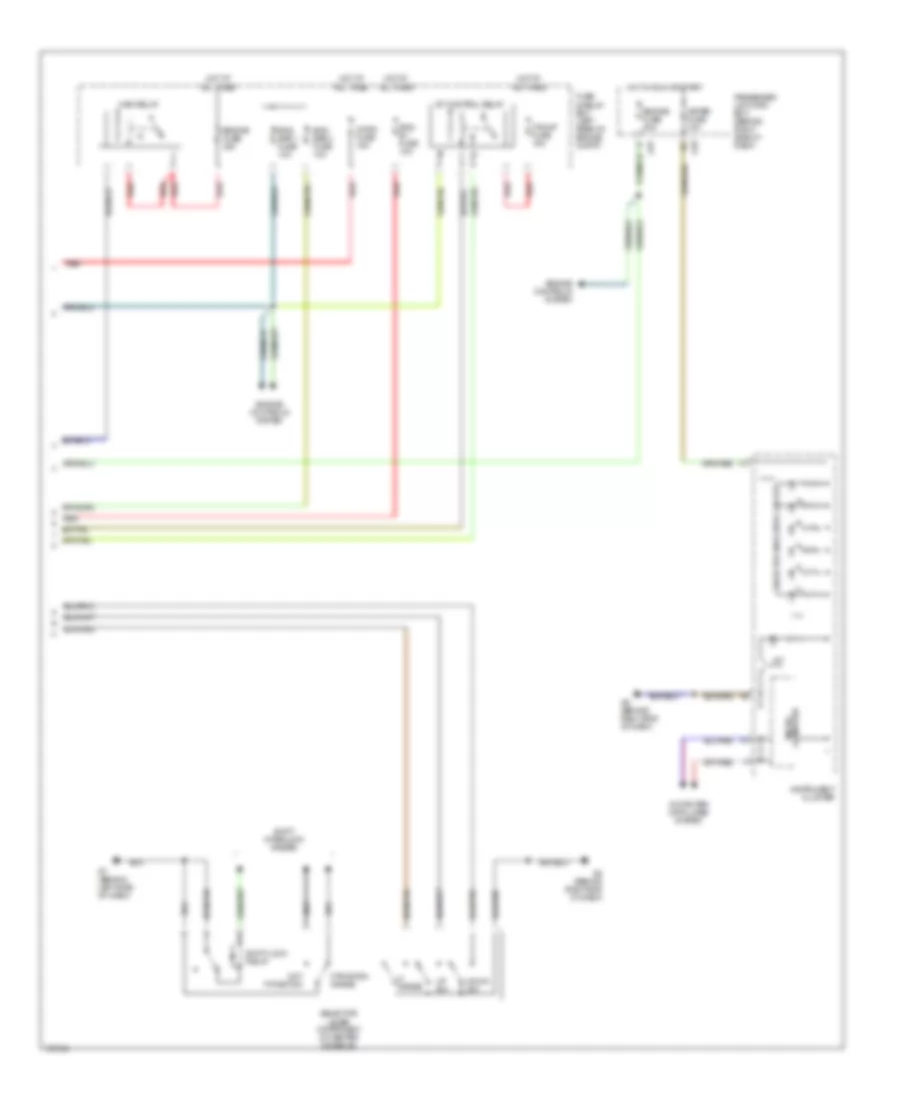
A/T Wiring Diagram (2 of 2) for Mazda 3 i 2004
List of elements for A/T Wiring Diagram (2 of 2) for Mazda 3 i 2004:
- 1-4
- A/t
- Computer data lines system
- Down sw
- Eng b + fuse 10a
- Eng bar 1 fuse 10a
- Eng bar 2 fuse 10a
- Engine controls system
- Engine fuse 20a
- Engine fuse 30a
- Et control relay
- F/pump fuse 15a
- Fuse & relay box (left rear of engine compt)
- G7 (behind left side of dash)
- G8 (behind right end of dash)
- Horn fuse 15a
- Hot at all times
- Hot in run or start
- Instrument cluster
- J-01
- J-03
- M range
- Main relay
- Meter fuse 10a
- Micro- computer
- Not p position
- P position range
- Passenger junction box (behind right side of dash)
- Red
- Selector indicator circuit
- Selector lever component (in center console)
- Shift interlock system
- Shift-lock relay
- Up sw
 English