TRANSMISSION
A/T Wiring Diagram (1 of 2) for Mazda 5 Grand Touring 2007

List of elements for A/T Wiring Diagram (1 of 2) for Mazda 5 Grand Touring 2007:
- (in transaxle)
- 1aa
- 1ai
- 1am
- 1at
- 1au
- 1av
- 1az
- 1ba
- Bcm (behind right side of dash)
- Computer data lines system
- Control valve body
- Engine controls system
- Exterior lights system
- Fuse block (behind right end of dash)
- G14 (rear of engine)
- G15
- Hot in on or acc
- Input/turbine speed sensor (on transaxle)
- J/c c-12 (behind center of dash)
- Meter fuse 10a
- Oil pressure switch (on left side of transaxle)
- Powertrain control module (rear of engine compt)
- R position
- Red
- Shift sol d
- Shift sol e red
- Shift/l fuse 5a
- Transaxle range switch (on transaxle)
- Vehicle speed sensor (on transaxle)
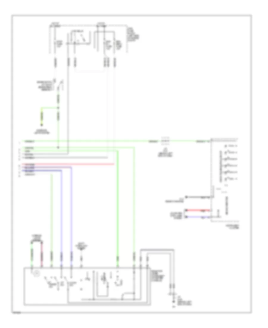
A/T Wiring Diagram (2 of 2) for Mazda 5 Grand Touring 2007
List of elements for A/T Wiring Diagram (2 of 2) for Mazda 5 Grand Touring 2007:
- 1-4
- Brake switch (at top of brake pedal assembly)
- Computer data lines system
- Down sw
- Eng b + fuse 10a
- Eng bar 2 fuse 15a
- Exterior lights system
- G14 (rear of engine)
- Hot at all times
- Instrument cluster
- Interior lights system
- J/c c-31 (behind left end of dash)
- J/c g-02 (behind left end of dash)
- M range sw
- Main fuse block (left side of engine compt)
- Main relay
- Microcomputer
- Not p position
- Red
- Selector indicator circuit
- Selector lever component (in center console)
- Shift interlock system
- Stop fuse 10a
- Up sw