AUTOMOTIVE ELECTRICIANS PORTAL

TRANSMISSION – Mazda 6 s 2005 – SYSTEM WIRING DIAGRAMS

TRANSMISSION

2.3L

2.3L, A/T Wiring Diagram for Mazda 6 s 2005

2.3L, AT Wiring Diagram for Mazda 6 s 2005 https://portal-diagnostov.com/license.html
https://portal-diagnostov.com/license.html Automotive Electricians Portal FZCO Automotive Electricians Portal FZCO
Download PDF file

List of elements for 2.3L, A/T Wiring Diagram for Mazda 6 s 2005:
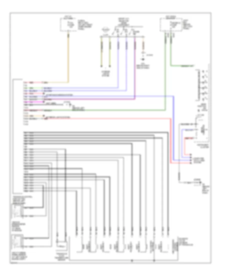
  • A/t ind
  • At main relay (left rear of engine compt)
  • Audio unit (w/o abs)
  • Computer data lines system
  • Control valve body
  • Eng+b fuse 7.5a
  • Exterior lights system
  • Fuse & relay box (on left front inner fender panel)
  • G10 (behind right end of dash)
  • G16 (at rear of engine)
  • G2 (behind left end of dash)
  • G2 (behind left side of dash)
  • Gear position ind
  • Hot at all times
  • Hot in on or start
  • Illum
  • Input/turbine speed sensor (at left side of engine compartment)
  • Instrument cluster
  • Interior lights system
  • Jb-01
  • Jb-02
  • Jc g-02
  • Jc g-03
  • Joint box (behind left kick panel)
  • Meter ig fuse 15a
  • Microcomputer
  • Oil pressure switch (at left rear of engine)
  • Pressure control solenoid
  • Range m
  • Red
  • Selector indicator circuit
  • Selector lever component (sport a/t)
  • Sensor temperature fluid transaxle
  • Shift solenoid a
  • Shift solenoid b
  • Shift solenoid c
  • Shift solenoid d
  • Shift solenoid e
  • Switch down
  • Switch up
  • Tcm fuse 10a
  • Transaxle control module (tcm) (behind left side of dash)
  • Transaxle range switch
  • Vehicle speedometer sensor (at left rear of engine)

3.0L

3.0L, A/T Wiring Diagram for Mazda 6 s 2005

3.0L, AT Wiring Diagram for Mazda 6 s 2005 https://portal-diagnostov.com/license.html
https://portal-diagnostov.com/license.html Automotive Electricians Portal FZCO Automotive Electricians Portal FZCO
Get access to all wiring diagrams of the carDownload PDF file

List of elements for 3.0L, A/T Wiring Diagram for Mazda 6 s 2005:

  • (behind left end of dash)
  • (not used)
  • (sport a/t) selector lever component
  • A/t ind
  • A10
  • A11
  • A12
  • A13
  • A14
  • A15
  • A16
  • B10
  • B11
  • B12
  • B13
  • B14
  • B15
  • B16
  • B17
  • B18
  • B19
  • B20
  • B21
  • B22
  • Computer data lines system
  • Dn sw
  • Exterior lights system
  • Fuse & relay box (on left front inner fender panel)
  • G10 (behind right end of dash)
  • G2 (behind left end of dash)
  • Gear position ind
  • Hot at all times
  • Hot in run or start
  • Illum
  • Input/turbine speed sensor (at left side of engine compt)
  • Instrument cluster
  • Interior lights system
  • Jb-01
  • Jb-02
  • Jc g-02
  • Jc g-03
  • Joint box (behind left kick panel)
  • Line pressure control solenoid
  • M range sw
  • Meter ig fuse 15a
  • Micro- computer
  • Nca
  • Pnk
  • Red
  • Selector indicator circuit
  • Shift solenoid a
  • Shift solenoid d
  • Shift solenoid e
  • Solenoid b shift
  • Solenoid c shift
  • Solenoid f shift
  • Solenoid tcc control
  • Solenoid valve (on rear of transaxle)
  • Starting/charging system
  • Tcm fuse 10a
  • Transaxle control module (tcm) (behind left side of dash)
  • Transaxle fluid temperature sensor
  • Up sw
  • Vehicle speedometer sensor (at rear of engine)