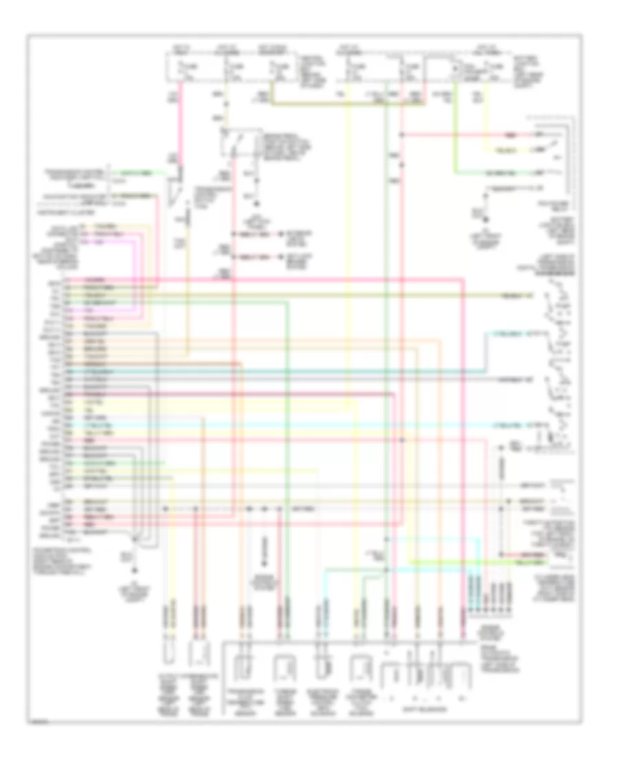
TRANSMISSION
A/T Wiring Diagram for Mazda B2300 SX 2001
List of elements for A/T Wiring Diagram for Mazda B2300 SX 2001:
- (dlc) (partial) (fastened to bottom of dash, near steering column)
- (left side of transmission) digital transmission range sensor
- 5r44e automatic transmission (left side of transmission)
- Anti-lock brakes system
- B-111
- Battery junction box (left rear of engine compt)
- Bpp
- Brake pedal position switch (behind left side of dash, above brake pedal)
- C-214
- C-215
- Central junction box (behind left side of dash)
- Cht
- Cylinder head temperature (cht) sensor (right side of cylinder head)
- Data link connector
- Dlc
- Dlc (+)
- Dlc (-)
- Electronic pressure control (epc) solenoid
- Engine controls system
- Epc
- Exterior lights system
- Fuse 10a
- Fuse 20a
- Fuse 25a
- Fuse 30a
- Fuse 7.5a
- G1 (left front of engine compt)
- G10 (left kick panel)
- Ground
- Hot at all times
- Hot in run
- Hot in run or start
- Instrument cluster
- Intermediate shaft speed (iss) sensor (left rear of trans)
- Iss
- Kapwr
- Malfunction indicator lamp (mil)
- Mil
- Nca
- O/d off
- Oss
- Output shaft speed (oss) sensor (left rear of trans)
- Pcm power diode
- Pcm power relay
- Power
- Powertrain control module (pcm) (right rear of engine compartment, through firewall)
- R p
- Red
- Shift solenoids
- Sig rtn
- Ss a
- Ss b
- Ss c
- Ss d
- Tcc
- Tcil
- Tcs
- Tft
- Throttle position (tp) sensor (top left front of engine, on throttle body)
- Torque converter clutch (tcc) solenoid
- Tr1
- Tr2
- Tr3a
- Tr4
- Transmission control indicator lamp (tcil)
- Transmission control switch (tcs)
- Transmission fluid temperature (tft) sensor
- Tss
- Turbine shaft speed (tss) sensor
- Vref
 English