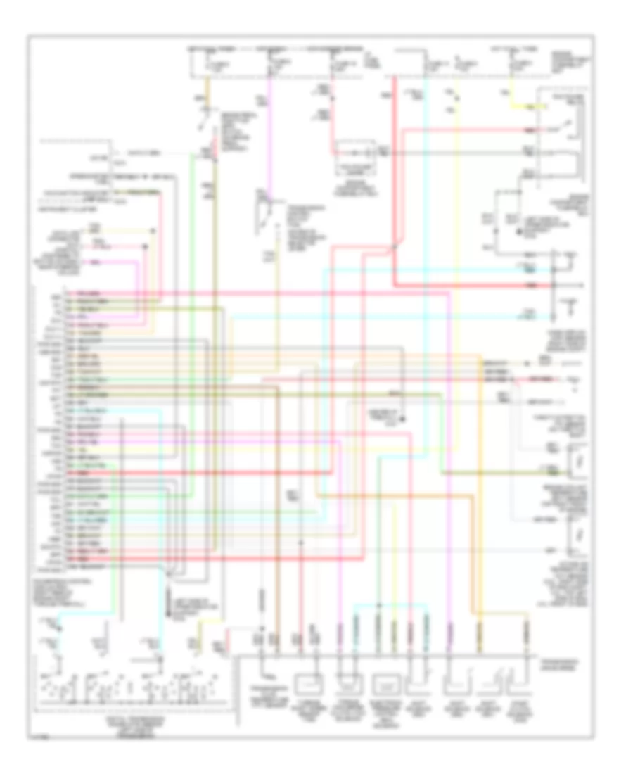
AUTOMOTIVE ELECTRICIANS PORTAL

TRANSMISSION – Mazda B4000 SE 2000 – SYSTEM WIRING DIAGRAMS

TRANSMISSION

4WD Wiring Diagram for Mazda B4000 SE 2000

4WD Wiring Diagram for Mazda B4000 SE 2000 https://portal-diagnostov.com/license.html
https://portal-diagnostov.com/license.html Automotive Electricians Portal FZCO Automotive Electricians Portal FZCO
Download PDF file

List of elements for 4WD Wiring Diagram for Mazda B4000 SE 2000:

  • (behind dash, right side of steering column) relay box
  • (left kick panel) g200
  • 1.1k ohms
  • 3.0l/ 4.0l only
  • 3.9k ohms
  • 4wd hi ind
  • 4wd ind ctrl
  • 4wd lo ind
  • 4wd mode sw
  • 4wd output
  • 4x4 shift control switch
  • A/t
  • Battery saver relay
  • Bpp sw input
  • Brake pedal position (bpp) switch (on brake pedal support)
  • C214
  • Ccw relay
  • Ccw rly ctrl
  • Clutch
  • Cw relay
  • Cw rly ctrl
  • Digital transmission range (dtr) sensor
  • Elc rly ctrl
  • Electric shift control module (behind center of dash)
  • Electric shift relay
  • Electronic shift motor assembly (on left rear of transmission)
  • Engine compartment fuse/relay box
  • Firewall) g121
  • Fuse 26 10a
  • Fuse 3 20a
  • Fuse 6 15a
  • Fuse 9 7.5a
  • G200 (left kick panel)
  • Generic electronic module (gem) (behind center of dash)
  • Hot at all times
  • Hot in run
  • I/p fuse panel
  • Illumination
  • Instrument cluster
  • Interior lights system (instrument illum- ination circuit)
  • M/t
  • Neutral sw in
  • Ohms
  • Powertrain contrtol module (pcm) (right rear of of eng compt through firewall)
  • Pulse vacuum hublock solenoid (near right headlight)
  • Pvhs
  • Relay box (behind dash, right side of steering column)
  • Rly ctrl
  • Shift motor
  • Shift motor sensor
  • Sw a input
  • Sw b input
  • Sw c input
  • Sw d input
  • T-221
  • T-223
  • T-224

A/T Wiring Diagram for Mazda B4000 SE 2000

AT Wiring Diagram for Mazda B4000 SE 2000 https://portal-diagnostov.com/license.html
https://portal-diagnostov.com/license.html Automotive Electricians Portal FZCO Automotive Electricians Portal FZCO
Get access to all wiring diagrams of the carDownload PDF file

List of elements for A/T Wiring Diagram for Mazda B4000 SE 2000:

  • (center of firewall) g121
  • (left side of upper radiator support) g108
  • (on end of transmission selector lever)
  • Bpp
  • Brake pedal postition (bpp) switch (on brake pedal support)
  • C214
  • C215
  • Ccs
  • Coast clutch solenoid (ccs)
  • Cse gnd
  • Data link connector (dlc) (partial) (fastened to bottom of dash, near steering column)
  • Digital transmission range (dtr) sensor (left side of transmission)
  • Dlc
  • Dlc (+)
  • Dlc (-)
  • Ect
  • Electronic pressure control (epc) solenoid
  • Engine compartment fuse/relay box
  • Engine coolant temperature (ect) sensor (top right front of engine)
  • Epc
  • Fuse 13 15a
  • Fuse 19 25a
  • Fuse 6 10a
  • Fuse 6 15a
  • Fuse 8 30a
  • Fuse 9 7.5a
  • Hot at all times
  • Hot in run
  • Hot in start or run
  • I/p fuse panel
  • Iat
  • Instrument cluster
  • Intake air temperature (iat) sensor (2.5l : right side of eng compt, 3.0l: top left side of eng, 4.0l: front of eng)
  • Kapwr
  • Maf
  • Maf rtn
  • Malfunction indicator lamp (mil)
  • Mass airflow (maf) sensor (right side of engine compt)
  • Mil
  • O/d ind
  • Pcm power diode
  • Pcm power relay
  • Powertrain control module (pcm) (right rear of engine compt through firewall)
  • Pwr gnd
  • Red
  • Shift solenoid (ss1)
  • Shift solenoid (ss2)
  • Shift solenoid (ss3)
  • Sig rtn
  • Speedometer (vss)
  • Ss1
  • Ss2
  • Ss3
  • Tcc
  • Tcil
  • Tcs
  • Tft
  • Throttle position (tp) sensor (on throttle body)
  • Torque converter clutch (tcc) solenoid
  • Transmission (4r44e 5r55e)
  • Transmission control switch (tcs)
  • Transmission fluid temperature (tft) sensor
  • Tss
  • Turbine shaft speed sensor (tss)
  • Vpwr
  • Vref
  • Vss