TRANSMISSION
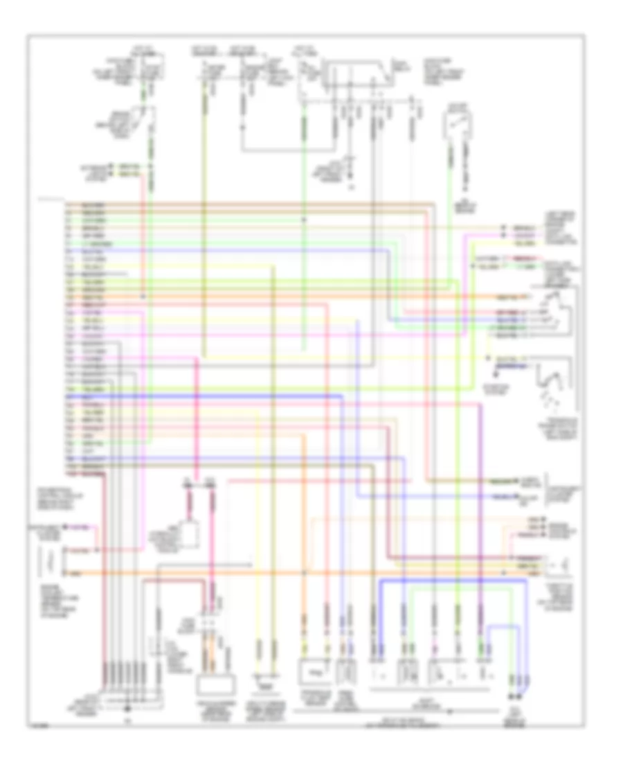
A/T Wiring Diagram for Mazda Protege DX 2002
List of elements for A/T Wiring Diagram for Mazda Protege DX 2002:
- (left rear corner of engine compt) data link connector
- Abs hydraulic unit/block control module
- Brake switch (behind left side of dash)
- C jb-01
- Check eng ind
- Data link connector 2 (lower left side of dash)
- Ec-at solenoid (on transaxle valve body)
- Engine controls system
- Engine coolant temperature sensor (on top rear of engine)
- Engine fuse 10a
- Exterior lights system
- Fb-01
- Fb-03
- Fb-04
- Fb-06
- G14 (left rear of engine)
- G4 (rear of engine)
- Hot at all times
- Hot in on or start
- Inj fuse 30a
- Input/turbine speed sensor (left side of engine compt)
- Instrument cluster system
- J/c x-04 (lower right front console)
- Jb-03
- Jb-04
- Jc-01 (front of left front fender)
- Jc-03 (rear of left front fender)
- Joint box (behind left kick panel)
- Main fuse block
- Main fuse block (on left front inner fender panel)
- Main relay
- Meter fuse 10a
- O/d off ind
- O/d off switch
- Powertrain control module (behind right side of dash)
- Pres- sure control solenoid
- Shift solenoids
- Starting system
- Stop fuse 15a
- Throttle position sensor (on top rear of engine)
- Transaxle fluid temp sensor
- Transaxle range switch (left side of eng compt)
- Vehicle speed sensor (near rear of engine)
- W/ abs
- W/o abs
 English