TRANSMISSION
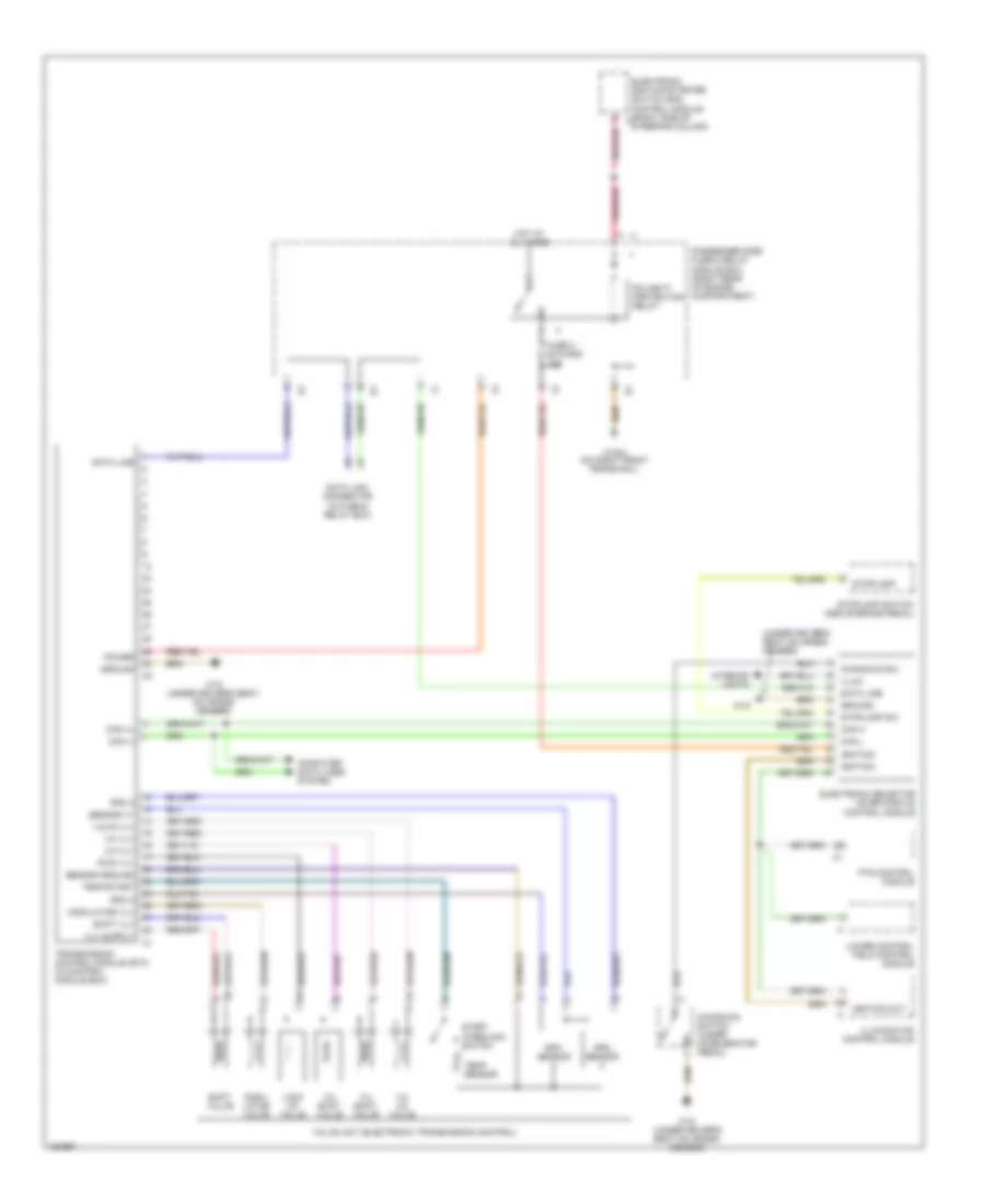
A/T Wiring Diagram, 5 Speed A/T for Mercedes-Benz E320 4Matic 2003

List of elements for A/T Wiring Diagram, 5 Speed A/T for Mercedes-Benz E320 4Matic 2003:
- (+)
- (-)
- 1-2/ 4-5 valve
- 2-3 shift valve
- 3-4 shift valve
- Can-c h
- Can-c l
- Circuit 87 relay, chassis
- Data link connector (dlc) (lower left side of dash)
- Di control module
- Diag
- Driver side sam control module with fuse & relay module (left rear of eng compt)
- Driver side sam control module with fuse/relay module (left rear of engine compartment)
- Electric steering lock control module (left front footwell)
- Electronic selector lever module control module (center console)
- Etc control module (right front footwell)
- Fuse 45 7.5a
- Fuse 7.5a
- Gear display sensor (under center console)
- Gnd
- Hot at all times
- Hot with circuit 87 relay chassis energized
- Keyless go start/stop pushbutton (if equipped)
- Left voltage distributor connector (left front door sill)
- Lock up valve
- Modu- lator valve
- Nca
- Rpm sensor
- Shift valve
- Sig
- Solid state
- Start interlock switch
- Temp sensor
- Valve unit (electronic transmission control)
- W15/1 (right front footwell)
A/T Wiring Diagram, Wagon for Mercedes-Benz E320 4Matic 2003
List of elements for A/T Wiring Diagram, Wagon for Mercedes-Benz E320 4Matic 2003:
- (under driver's seat on cross- member)
- 1-2/ 4-5 valve
- 1-2/4-5 vlv
- 2-3 shift valve
- 2-3 vlv
- 3-4 shift valve
- 3-4 vlv
- A pnk/red
- Can (+)
- Can (-)
- Can h
- Can l
- Computer data lines system
- Data line
- Data link connector (in fuse & relay box)
- Electronic ignition-starter switch (eis) control module (right side of steering column)
- Electronic selector lever module control module
- Fuse 3 etc/ads 10a
- Ground
- Hot at all times
- Ignition
- Ignition out
- Illum
- Illumination control module
- Interior lights
- Kickdown sw
- Kickdown switch (under accelerator pedal)
- Lock up valve
- Lower control field control module
- Modu- lator valve
- Modulator vlv
- Passenger side fuse & relay module box (right rear of engine compartment)
- Pnk/red
- Polarity protection relay
- Power
- Pts control module
- Pwm vlv
- Rpm 2
- Rpm 3
- Rpm sensor
- Sensor ground
- Sensor v+
- Shift valve
- Shift vlv
- Start interlock switch
- Stoplamp
- Stoplamp sw
- Stoplamp switch (above brake pedal)
- Temp sensor
- Temp/start
- Transmission control module (etc) (in control module box)
- Valve unit (electronic transmission control)
- W16/4 (on right front frame rail)
- W18
- W18 (under driver's seat on cross- member)
- W18 (under driver's seat, on cross- member)