TRANSMISSION
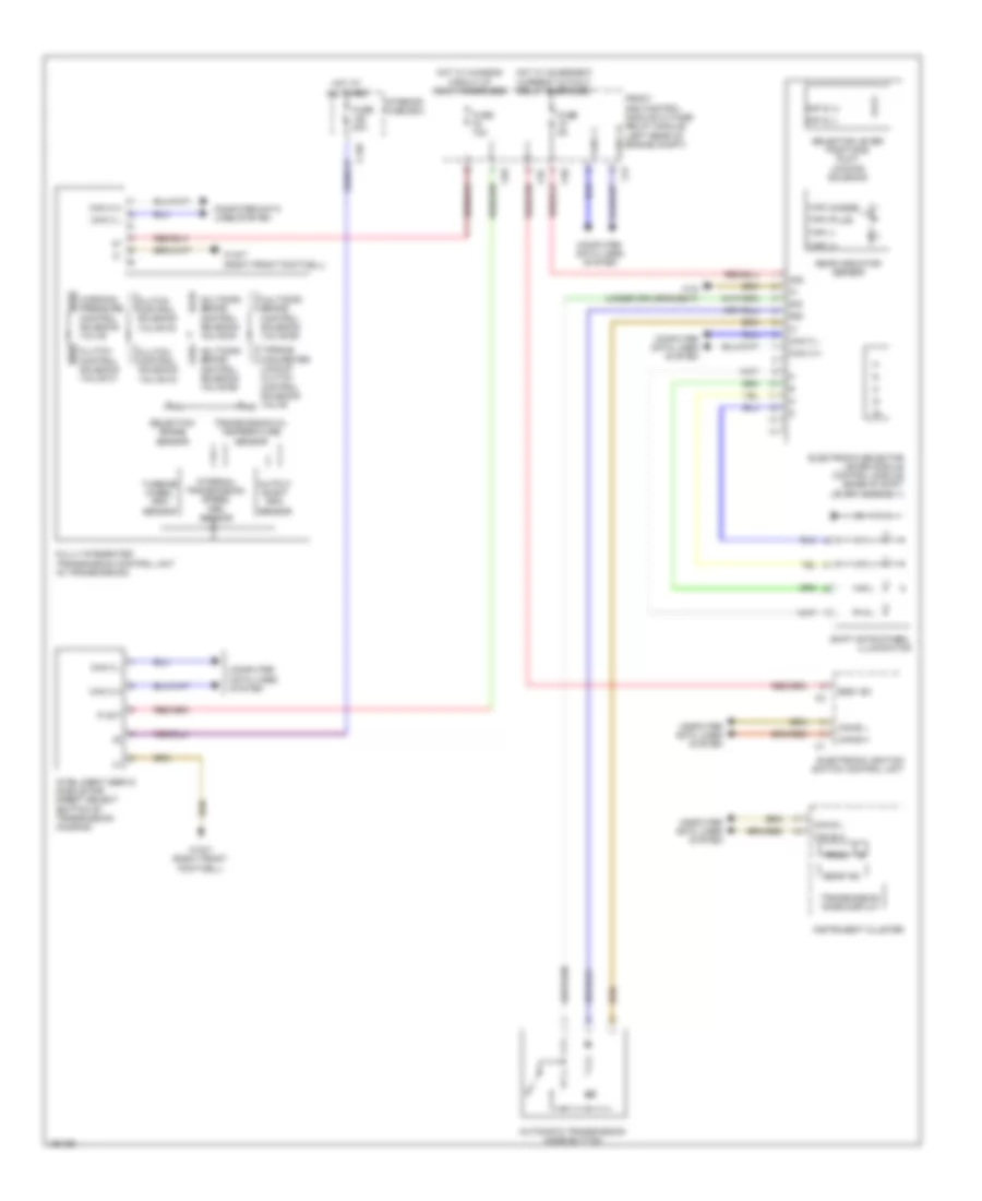
Transmission Wiring Diagram, Convertible for Mercedes-Benz E550 4Matic 2014

List of elements for Transmission Wiring Diagram, Convertible for Mercedes-Benz E550 4Matic 2014:
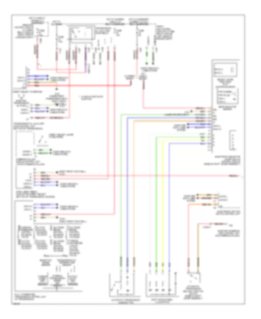
Transmission Wiring Diagram, Coupe for Mercedes-Benz E550 4Matic 2014
List of elements for Transmission Wiring Diagram, Coupe for Mercedes-Benz E550 4Matic 2014:
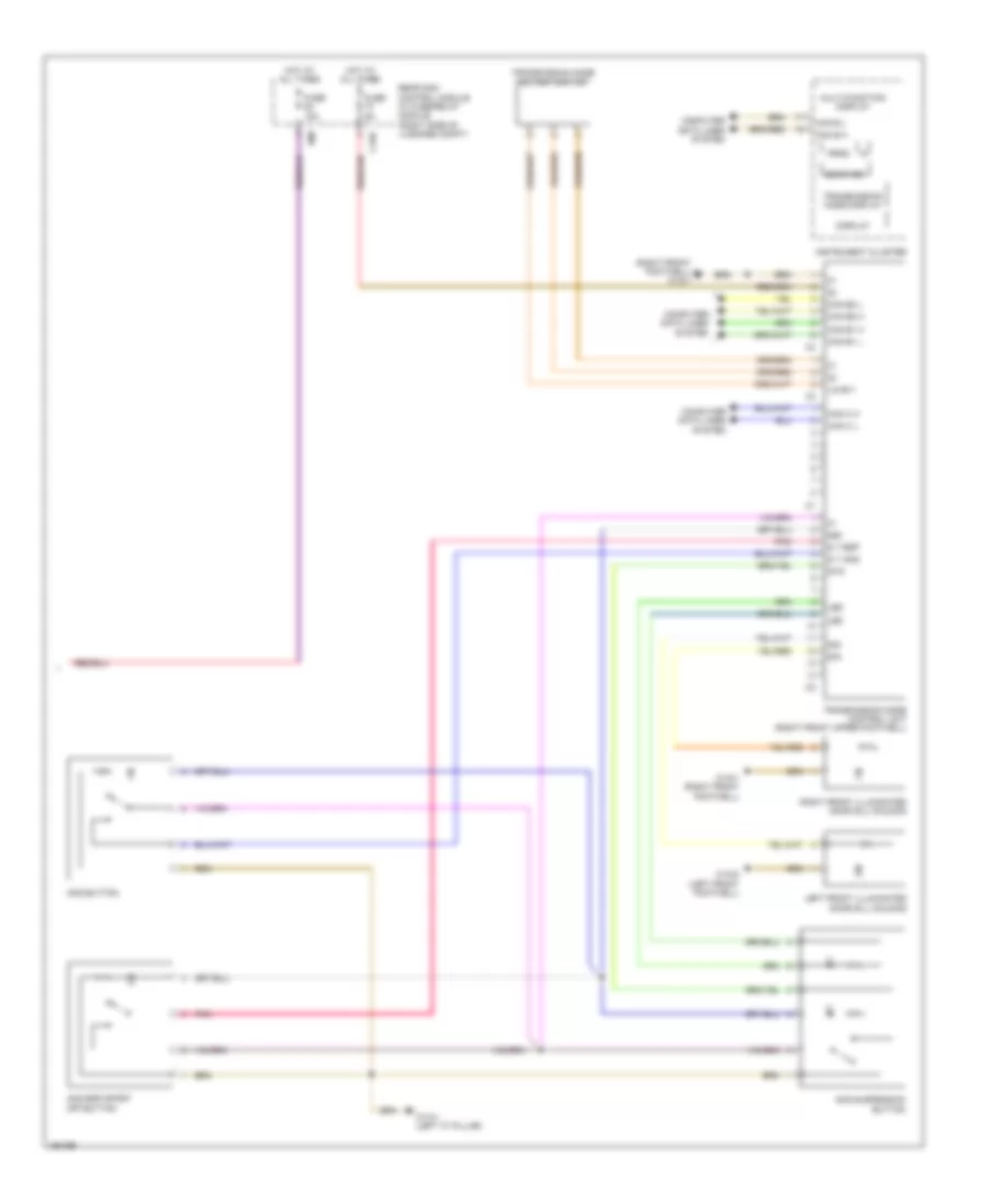
Transmission Wiring Diagram, Sedan (1 of 2) for Mercedes-Benz E550 4Matic 2014
List of elements for Transmission Wiring Diagram, Sedan (1 of 2) for Mercedes-Benz E550 4Matic 2014:
Transmission Wiring Diagram, Sedan (2 of 2) for Mercedes-Benz E550 4Matic 2014
List of elements for Transmission Wiring Diagram, Sedan (2 of 2) for Mercedes-Benz E550 4Matic 2014: