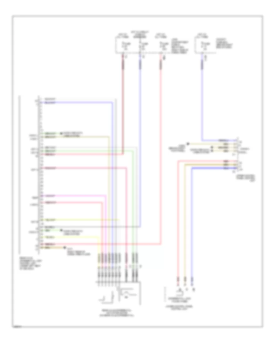
TRANSMISSION
A/T Wiring Diagram for Mercedes-Benz GL350 2012

List of elements for A/T Wiring Diagram for Mercedes-Benz GL350 2012:
- (right side of engine compt) (3.0l diesel) w2
- B1 brake control solenoid valve (vgs)
- B2 brake control solenoid valve (vgs)
- B3 brake control solenoid valve (vgs)
- Can-b h
- Can-b l
- Can-c h
- Can-c l
- Computer data lines system
- Eis (ezs) control unit
- Electric control unit (vgs) (in transmission housing)
- Engine compartment fuse & relay box (right side of engine compt)
- Fully integrated transmission control (vgs) control unit
- Fuse 15a
- Fuse 30a
- Fuse 7.5a
- Hot at all times
- Hot w/ circuit 15 relay energized
- Hot w/ coolant circulation pump relay energized
- Intelligent servo module (direct select) (left side of transmission housing)
- Internal speed sensor (vgs)
- Ism
- K1 clutch control solenoid valve (vgs)
- K2 clutch control solenoid valve (vgs)
- K3 clutch control solenoid valve (vgs)
- M2 x25/2-c2
- Mr1
- Mr3
- Mr4
- Output speed sensor (vgs)
- Red
- Selection range sensor (vgs)
- Torque converter lockup clutch control solenoid valve (vgs)
- Transmission oil cooler circulation pump
- Transmission oil temp sensor (vgs)
- Turbine speed sensor (vgs)
- Upper control panel control module
- W16/3 (4.6l & 5.5l) (left rear of engine compt)
- W2 (3.0l diesel) (right side of engine compt)
- W2 (right side of engine compt)
- Working pressure control solenoid valve (vgs)
- X18
- X22/6
Rear Differential Lock Wiring Diagram for Mercedes-Benz GL350 2012
List of elements for Rear Differential Lock Wiring Diagram for Mercedes-Benz GL350 2012:
- (-)
- C13b
- Can-b h
- Can-b l
- Can-c h
- Can-c l
- Cockpit fuse box (behind right end of dash)
- Computer data lines system
- Differential lock thumb wheel
- Fuse 30a
- Fuse 5a
- H sig 1
- H sig 2
- Hot at all times
- Hot w/ circuit 15 relay energized
- Lin
- Load compartment fuse & relay box (right side of cargo area)
- Lower control panel control unit
- Mot a
- Mot b
- Ms4
- Nca
- Rear axle differential actuator motor (on rear axle differential)
- Rear axle differential lock control unit (under left seat of 3rd row)
- Red
- Temp
- Upper control panel control unit
- W29/2 (behind right kick panel)
- W7/7 (right rear of cargo area floor)
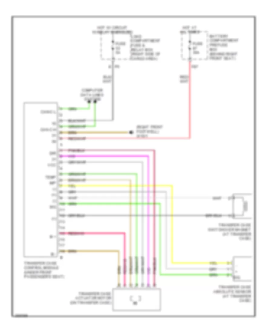
Transfer Case Wiring Diagram for Mercedes-Benz GL350 2012
List of elements for Transfer Case Wiring Diagram for Mercedes-Benz GL350 2012:
- (+)
- (-)
- (right front footwell) w15/1
- Battery compartment prefuse box (behind right front seat)
- Can-c h
- Can-c l
- Computer data lines system
- Dir
- F87
- Fuse 30a
- Fuse 5a
- Hot at all times
- Hot w/ circuit 15 relay energized
- Imp
- Load compartment fuse & relay box (right side of cargo area)
- M +
- M -
- Sig
- Temp
- Transfer case absolute sensor (at transfer case)
- Transfer case actuator motor (on transfer case)
- Transfer case control module (under front passenger's seat)
- Transfer case switchover magnet (at transfer case)
- Vcc