TRANSMISSION
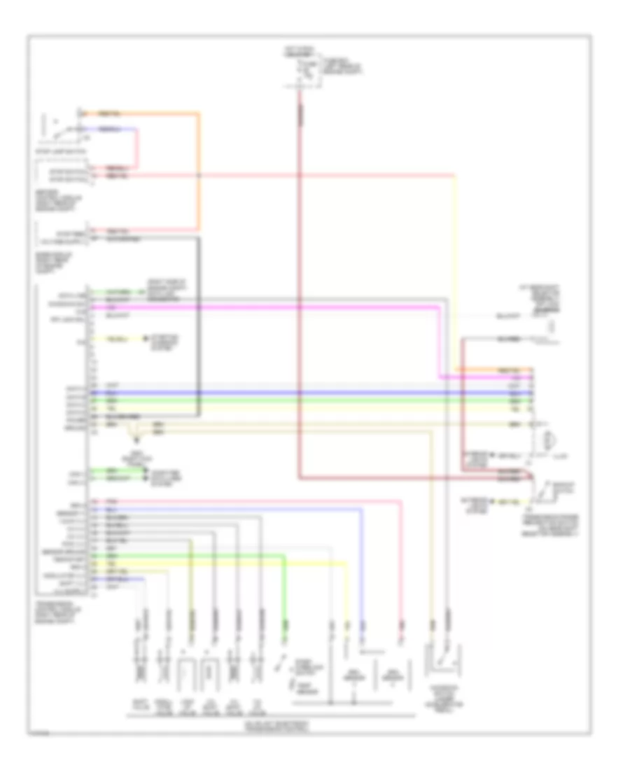
A/T Wiring Diagram for Mercedes-Benz S500 1997
List of elements for A/T Wiring Diagram for Mercedes-Benz S500 1997:
- (at gear shift selector assembly) r/p lock solenoid
- (right side of engine compt) data link connector
- 1-2/ 4-5 valve
- 1-2/4-5 vlv
- 2-3 shift valve
- 2-3 vlv
- 3-4 shift valve
- 3-4 vlv
- Backup switch
- Base module (right rear of engine compt)
- Can (+)
- Can (-)
- Computer data lines system
- Data a
- Data b
- Data c
- Data d
- Data line
- Esp/sps control module (right rear of engine compt)
- Exterior lights system
- Fuse 15a
- Fuse box (left rear of engine compt)
- G203 (right kick panel)
- Ground
- Hot in run or start
- Illum
- Interior lights system
- Kickdown sw
- Kickdown switch (under accelerator pedal)
- Lock up valve
- Modul- ator valve
- Modulator vlv
- P/n
- Pnk
- Power
- Pwm vlv
- R/p lock sol
- Rpm 2
- Rpm 3
- Rpm sensor
- Sensor ground
- Sensor v+
- Shift valve
- Shift vlv
- Start interlock switch
- Starting/ charging system
- Stop feed
- Stop lamp switch
- Stop switch
- Temp sensor
- Temp/start
- Transmission control module (right rear of engine compt)
- Transmission range recognition switch (on gear shift selector assembly)
- Valve unit (electronic transmission control)
- W/s
 English