TRANSMISSION
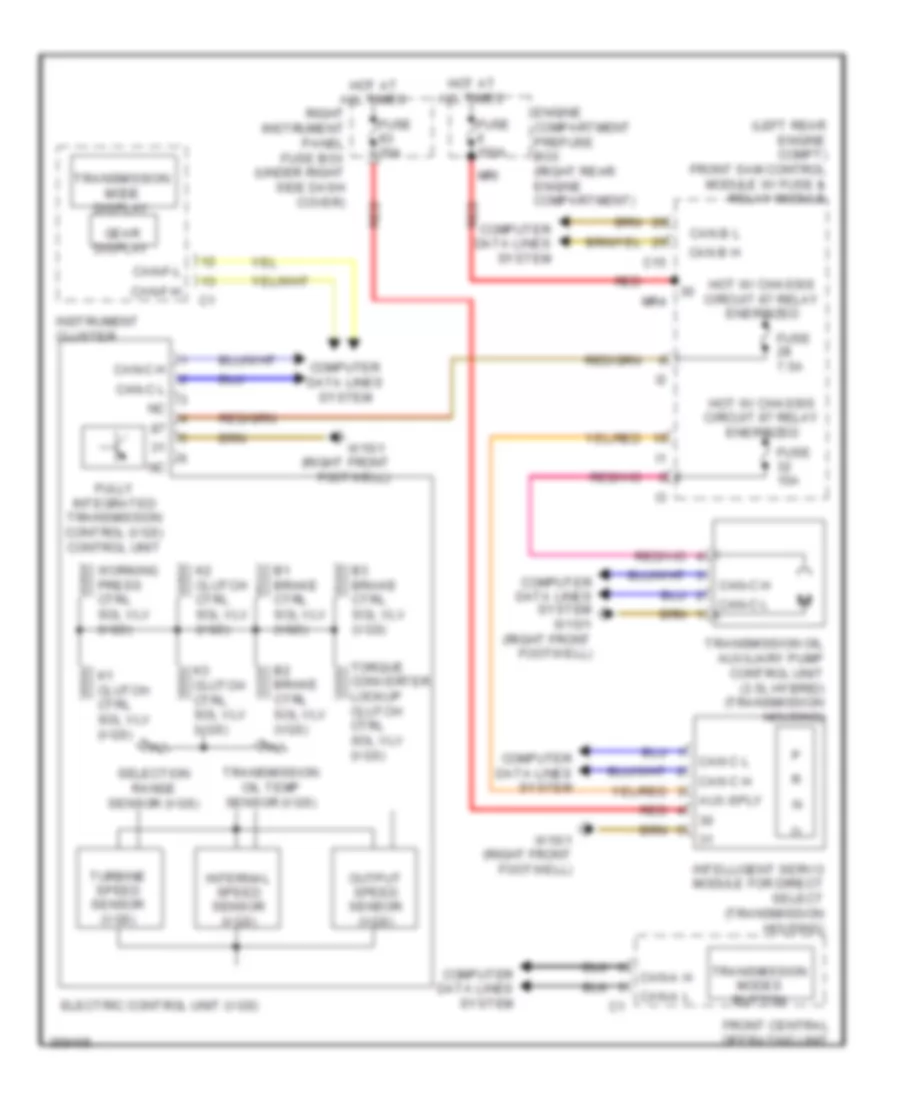
Transmission Wiring Diagram for Mercedes-Benz S550 2011
List of elements for Transmission Wiring Diagram for Mercedes-Benz S550 2011:
- (left rear engine compt) front sam control module w/ fuse & relay module
- (right front footwell)
- Aux-sply
- B1 brake ctrl sol vlv (vgs)
- B2 brake ctrl sol vlv (vgs)
- B3 brake ctrl sol vlv (vgs)
- C15
- Can b h
- Can b l
- Can c h
- Can c l
- Can-a h
- Can-a l
- Can-c h
- Can-c l
- Can-f-h
- Can-f-l
- Computer data lines system
- Computer data lines system w15/1 (right front footwell)
- Electric control unit (vgs)
- Engine compartment prefuse box (right rear engine compartment)
- Front central operating unit
- Fully integrated transmission control (vgs) control unit
- Fuse 150a
- Fuse 15a
- Fuse 30a
- Fuse 7.5a
- Gear display
- Hot at all times
- Hot w/ chassis circuit 87 relay energized
- Instrument cluster
- Intelligent servo module for direct select (transmission housing)
- Internal speed sensor (vgs)
- K1 clutch ctrl sol vlv (vgs)
- K2 clutch ctrl sol vlv (vgs)
- K3 clutch ctrl sol vlv (vgs)
- Mr4
- Mri
- Output speed sensor (vgs)
- Red
- Right instrument panel fuse box (under right side dash cover)
- Selection range sensor (vgs)
- Torque converter lockup clutch ctrl sol vlv (vgs)
- Transmission mode display
- Transmission modes button
- Transmission oil auxiliary pump control unit (3.5l hybrid) (transmission housing)
- Transmission oil temp sensor (vgs)
- Turbine speed sensor (vgs)
- W15/1
- W15/1 (right front footwell)
- Working press ctrl sol vlv (vgs)
 English