TRANSMISSION
A/T Wiring Diagram for Mercedes-Benz SLK320 2002
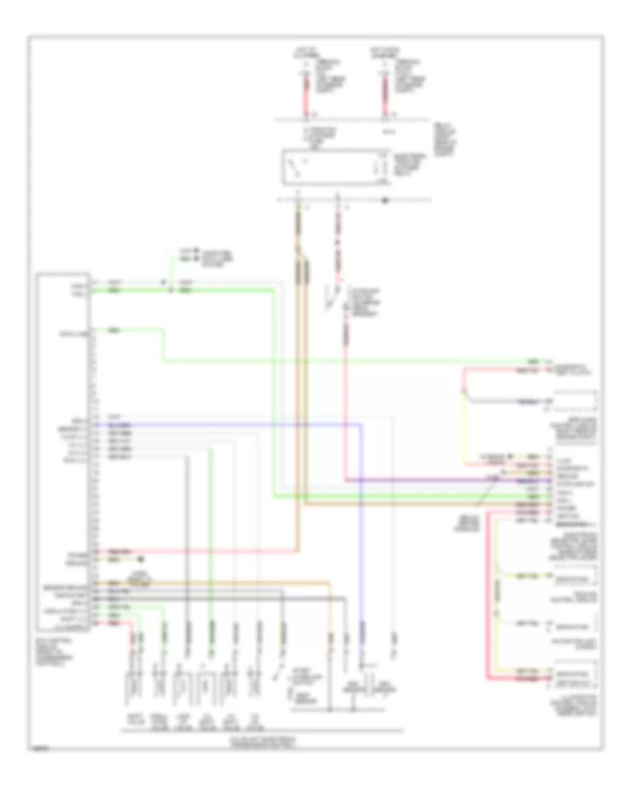
List of elements for A/T Wiring Diagram for Mercedes-Benz SLK320 2002:
- (below center console)
- 1-2/ 4-5 valve
- 1-2/4-5 vlv
- 2-3 shift valve
- 2-3 vlv
- 3-4 shift valve
- 3-4 vlv
- Backup sig
- Backup sw
- Can h
- Can l
- Computer data lines system
- Data line
- Diagnostic
- Diagnostic test clutch
- Electronic selector lever control module (base of gear selector lever)
- Electronic traction systems relay
- Esp & bas control module (right rear of engine compt)
- Etc control module (front of passenger's footwell)
- Ground
- Hot at all times
- Hot in run or start
- Ignition
- Ignition out
- Illum
- Illumination control module (integral with headlamp sw)
- Interior lights
- Lock up valve
- Modul- ator valve
- Modulator vlv
- Navigation unit & radio
- Pnk/red
- Power
- Pwm vlv
- Red
- Relay module (right rear of engine compt)
- Rpm 2
- Rpm 3
- Rpm sensor
- Sensor ground
- Sensor v+
- Shift valve
- Shift vlv
- Start interlock switch
- Stoplamp sw
- Stoplamp switch (on brake pedal bracket)
- Tele aid control module
- Temp sensor
- Temp/start
- Terminal block (x12/1) (left rear of engine compt)
- Terminal block (x4) (left rear of engine compt)
- Traction systems fuse 15a
- Valve unit (electronic transmission control)
- W12
- W29/2 (right "a" pillar)
 English