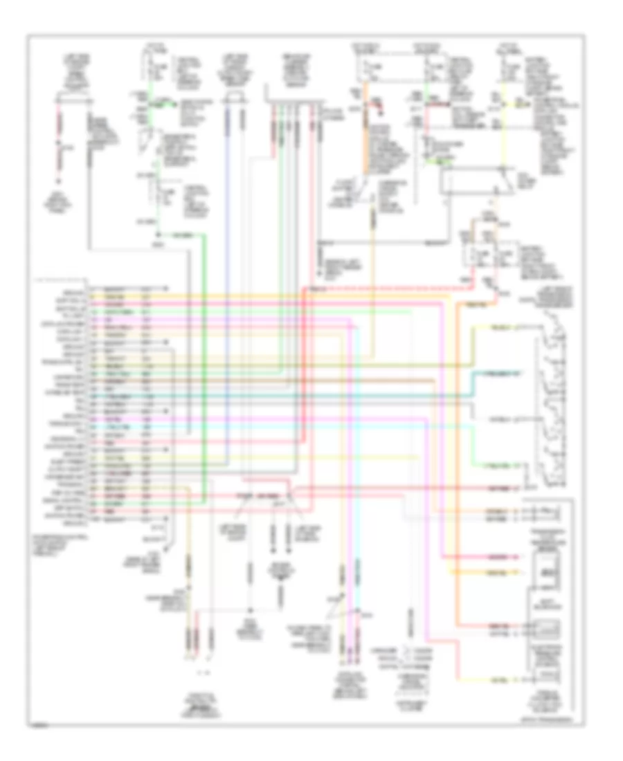
TRANSMISSION
A/T Wiring Diagram for Mercury Grand Marquis GS 2004
List of elements for A/T Wiring Diagram for Mercury Grand Marquis GS 2004:
- (behind air cleaner assembly) mass air- flow (maf) sensor
- (in dash panel to headlamp junc- tion harn, near breakout to c1047)
- (left rear of engine compt)
- (left side of engine compt)
- (left side of tran- smission)
- (left side of trans- mission) output shaft speed (oss) sensor
- (left side of transmission) digital transmission range sensor
- (police)
- (rear of left front fender apron) g101
- 4r70w transmission
- Analog
- Battery junction box (bjb) (right front of eng compt, behind battery)
- Battery junction box (bjb) (right front of engine compt, behind battery)
- Bpp switch
- Brake pedal position (bpp) switch (top of brake pedal support)
- C220b
- C2220b
- Central junction box (cjb) (below dash, left of steering column)
- Central junction box (left of steering column)
- Data link +
- Data link -
- Data link connector (partial) (behind left side of dash)
- Data link power
- Deactivator switch & multi- function switch
- Digital
- Elect press
- Electronic pressure control solenoid
- Engine controls system
- Floor shifter (w/ center console)
- Fuse 15a
- Fuse 20a
- Fuse 25a
- Fuse 30a
- G101 (rear of left front fender apron)
- G201 (behind right kick panel)
- Ground
- Hot at all times
- Hot in run or start
- Ignition coil, passive anti-theft transceiver
- Ignition power
- Instrument cluster
- Intake air temp
- Lighting control module, volt meter, oil pressure gauge, warning lamp module & instrument cluster
- Maf return
- Maf sensor sig
- Marauder
- Output shaft
- Overdrive cancel indicator
- Overdrive cancel switch (w/o center console)
- Pcm power diode
- Pcm power relay
- Powertrain control module (pcm) (left side of firewall)
- Powertrain control module, data link connector, natural gas module
- R p
- Red
- Ref voltage
- S109
- S110
- S115
- S117
- S118
- S123 (near breakout to c1033)
- S126 (near breakout near coil on plug 4)
- S130
- S134
- S135
- S146
- S147
- S265
- S276
- S283
- Shift sol a
- Shift sol b
- Shift solenoids
- Signal control
- Speed control actuator
- Ss a
- Ss b
- Tci lamp
- Throttle position (tp) sensor (left side of throttle body)
- Torque conv
- Torque converter clutch (tcc) solenoid
- Tps signal
- Tr1
- Tr2
- Tr3
- Tr4
- Trans cntrl sw
- Trans temp
- Transmission fluid temperature sensor
- Vss signal (+)
 English