TRANSMISSION
4.0L
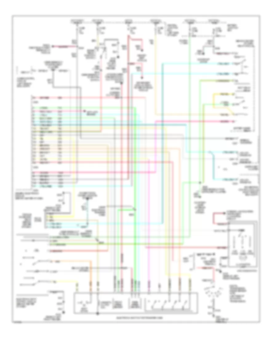
4.0L SOHC, A/T Wiring Diagram, 5R55E for Mercury Mountaineer 2001

List of elements for 4.0L SOHC, A/T Wiring Diagram, 5R55E for Mercury Mountaineer 2001:
- (100 mm from throttle position breakout)
- (center of firewall)
- (eng ctntl harn, near top of cylinder head) s124
- (left radiator support) g101
- (near breakout to 16-pin conn at rear of eng compt)
- (near breakout to 4wabs module)
- (near breakout to fuel inj 6) (sohc only)
- (sohc)
- 4wabs module (left side of eng compt)
- 5r55e automatic transmission
- A/c system
- Air condi- tioning & engine controls systems
- Anti-lock brakes system
- Back-up lamp switch, drl module, rear window defog relay, parking aid module
- Battery junction box
- Brake pedal position switch
- C172
- C286
- C287
- Canister vent solenoid
- Central junction box (left side of dash)
- Data link connector (partial) (left side of dash)
- Day/night mirror
- Digital transmission range sensor (left side of transmission)
- Dimmer relay & instrument cluster
- Electronic pressure control solenoid
- Engine controls system
- Engine controls system (ignition)
- Engine coolant temperature sensor (front of engine left of throttle body)
- Fuse 10a
- Fuse 15a
- Fuse 25a
- Fuse 7.5a
- G100 (rear of left front fender)
- G101 (left radiator support)
- G201
- Hot at all times
- Hot in run
- Hot in run or start
- Instrument cluster
- Instrument cluster system (headlamp switch)
- Malfunction indicator lamp (check engine)
- Mass air flow sensor (right side of eng compt)
- Maxi fuse 30a
- O/d off indicator lamp (tcil)
- Output shaft speed sensor (left rear of transmission) (sohc only)
- Passive anti-theft system module
- Pcm power relay
- Pcm power relay diode
- Powertrain control module (through firewall)
- R p
- Rear axle sensor
- Red
- Red/pnk
- S101 (in breakout for pcm)
- S105
- S123 (near fuel pump relay breakout)
- S136 (405 mm from bmap sensor breakout)
- S137
- S142 (right rear of eng)
- S146
- S147 (near breakout to auxiliary relay box 3)
- S166
- S167 (near breakout to fuel injector 6)
- S168
- S179
- S180
- S205
- S206
- S207
- S213
- S215 (near breakout to ignition switch)
- S230
- Sens hi
- Sens lo
- Shift solenoid a
- Shift solenoid b
- Shift solenoid c
- Shift solenoid d
- Throttle postion sensor (attached to throttle body)
- Torque converter clutch solenoid
- Transmission control switch
- Transmission fluid temperature sensor
- Turbine shaft speed sensor (sohc)
- Vs out
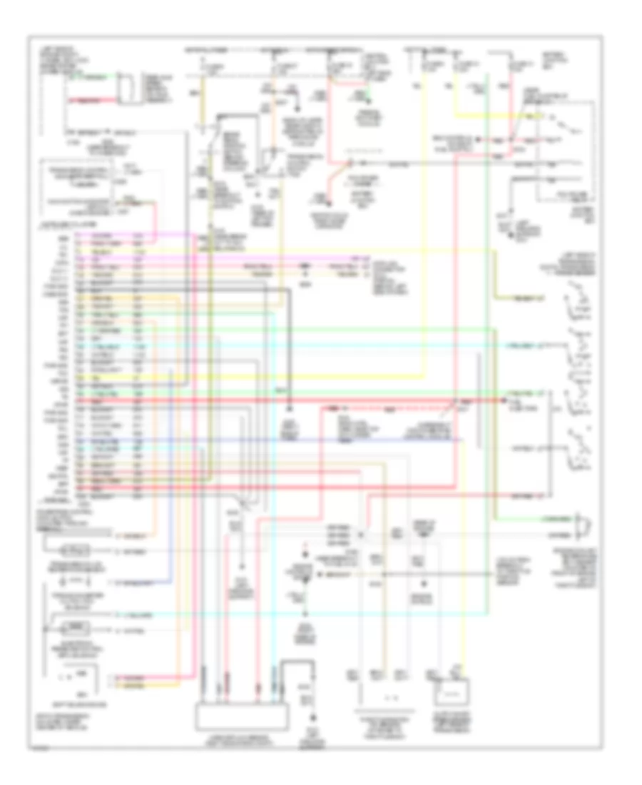
4WD Wiring Diagram for Mercury Mountaineer 2001
List of elements for 4WD Wiring Diagram for Mercury Mountaineer 2001:
- (behind center of dash) relay module
- (below center of dash)
- (in break out to gem) s250
- (left side of automatic transmission)
- (near break out to relay module)
- (near breakout for instrument cluster)
- (near breakout to instrument cluster) s247
- (near breakout to radio)
- (near electronic transfer case)
- 1.1k ohms
- 3.9k ohms
- 4.0l
- 4wabs control module (left side of eng compt)
- 4wd mode switch
- 4x4 high range ind
- 4x4 low range ind
- 4x4 low range ind c202
- 87a
- A/t
- Accy delay relay
- Anti-lock brakes
- Battery junction box
- Battery saver relay
- Brake pedal position switch
- C280
- C282
- C283
- C286
- Central junction box (left side of dash)
- Courtesy lamps (interior lights system)
- Digital transmission range sensor (dtr)
- Driver seat module, radio, power antenna module
- Electronic shift control module (behind center of dash)
- Electronic shift motor transfer case
- Front speed sensor
- Fuse 10a
- Fuse 7.5a
- G100 (rear of left front fender)
- G201 (center of firewall)
- Generic electronic module (behind center of dash)
- H2l
- Hot at all times
- Hot in accy or run
- Hot in start
- Illumination lamp
- Instrument cluster
- Interior lights system (instrument illumination circuit)
- L2h
- Liftgate wiper/ washer switch, multi-function switch
- M/t
- Magnetic clutch coil
- Maxi fuse 20a
- Maxi fuse 30a
- Memory seat module
- Mode
- Moonroof motor
- Ohms
- Power tops & power windows systems
- Powertrain control module (right side of eng compt)
- Radio, remote anti-theft personality module
- Rear speed sensor
- S108
- S200
- S215 (near breakout to ignition switch)
- S230
- S236
- S245
- S246
- S249
- S251
- S252
- S259
- S282
- Shift motor
- Solid state
- Speedo/ odometer c287
- Torque on demand relay (behind center of dash)
- Vss out
5.0L
4WD Wiring Diagram for Mercury Mountaineer 2001
List of elements for 4WD Wiring Diagram for Mercury Mountaineer 2001:
- (behind center of dash) relay module
- (below center of dash)
- (in break out to gem) s250
- (left side of automatic transmission)
- (near break out to relay module)
- (near breakout for instrument cluster)
- (near breakout to instrument cluster) s247
- (near breakout to radio)
- (near electronic transfer case)
- 1.1k ohms
- 3.9k ohms
- 4.0l
- 4wabs control module (left side of eng compt)
- 4wd mode switch
- 4x4 high range ind
- 4x4 low range ind
- 4x4 low range ind c202
- 87a
- A/t
- Accy delay relay
- Anti-lock brakes
- Battery junction box
- Battery saver relay
- Brake pedal position switch
- C280
- C282
- C283
- C286
- Central junction box (left side of dash)
- Courtesy lamps (interior lights system)
- Digital transmission range sensor (dtr)
- Driver seat module, radio, power antenna module
- Electronic shift control module (behind center of dash)
- Electronic shift motor transfer case
- Front speed sensor
- Fuse 10a
- Fuse 7.5a
- G100 (rear of left front fender)
- G201 (center of firewall)
- Generic electronic module (behind center of dash)
- H2l
- Hot at all times
- Hot in accy or run
- Hot in start
- Illumination lamp
- Instrument cluster
- Interior lights system (instrument illumination circuit)
- L2h
- Liftgate wiper/ washer switch, multi-function switch
- M/t
- Magnetic clutch coil
- Maxi fuse 20a
- Maxi fuse 30a
- Memory seat module
- Mode
- Moonroof motor
- Ohms
- Power tops & power windows systems
- Powertrain control module (right side of eng compt)
- Radio, remote anti-theft personality module
- Rear speed sensor
- S108
- S200
- S215 (near breakout to ignition switch)
- S230
- S236
- S245
- S246
- S249
- S251
- S252
- S259
- S282
- Shift motor
- Solid state
- Speedo/ odometer c287
- Torque on demand relay (behind center of dash)
- Vss out
5.0L, A/T Wiring Diagram, 4R70W for Mercury Mountaineer 2001
List of elements for 5.0L, A/T Wiring Diagram, 4R70W for Mercury Mountaineer 2001:
- (100 mm from breakout to throttle position sensor)
- (engine cntrls)
- (in breakout for powertrain control module)
- (left radiator support) g101
- (left side of engine compt) 4 wheel anti-lock brake system (4wabs) module
- (left side of transmission) digital transmission range sensor
- (near fuel pump relay breakout)
- (rear of engine) s130
- 4r70w transmission (mounted under center of vehicle)
- Back-up lamps, rear window defrost relay, parking aid module
- Battery junction box
- Bpp
- Brake pedal position switch (behind steering column)
- Breakout to ignition switch)
- C186
- C202
- C286
- C287
- Case gnd
- Central junction box (left side of dash)
- Data
- Data link connector (dlc) (partial) (behind left side of dash)
- Dlc (+)
- Dlc (-)
- Ect
- Electronic pressure control (epc) solenoid
- Eng controls, a/c relay, fuel pump rly
- Engine controls system
- Engine coolant temperature (ect) sensor (mounted on front of engine, left of throttle body)
- Epc
- Fuel injectors
- Fuse 10 30a
- Fuse 13 15a
- Fuse 19 25a
- Fuse 27 15a
- Fuse 6 10a
- Fuse 9 7.5a
- G100 (rear of left frt fender)
- G101 (left radiator support)
- G201 (right side of dash)
- Hot at all times
- Hot in run
- Hot in start or run
- Ignition coils, radio noise capacitor
- Instrument cluster
- Kapwr
- Maf
- Malfunction indicator lamp (mil) (check engine)
- Mass air flow sensor (right side of eng compt)
- Mil
- Od off
- Oss
- Output shaft speed sensor (left rear of transmission)
- Passive anti-theft module
- Pcm power diode
- Pcm power relay
- Powertrain control module (pcm) (mounted through firewall)
- Pwr gnd
- R p
- Rear axle speed sensor (on axle assembly)
- Red
- Red/pnk
- S101
- S105
- S123
- S124 (eng cntrl harn, near top of cylinder head)
- S137
- S142 (right rear of engine)
- S146
- S166 (near breakout to fuel inj 6)
- S168 (near breakout to 4wabs mod)
- S205
- S206
- S207
- S230
- Shift solenoids (ss)
- Sig rtn
- Ssa
- Ssb
- Tcc
- Tcil
- Tcs
- Tft
- Throttle position (tp) sensor (attached to throttle body)
- Torque converter clutch (tcc) solenoid
- Tr1
- Tr2
- Tr3
- Transmission control indicator lamp (tcil)
- Transmission control switch (tcs)
- Transmission fluid temperature sensor
- Vpwr
- Vref
- Vss