TRANSMISSION
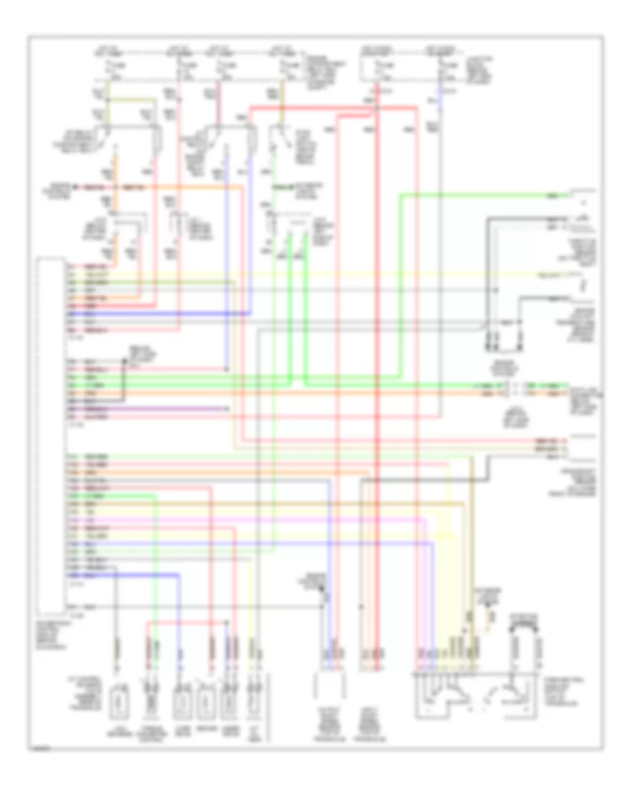
A/T Wiring Diagram for Mitsubishi Lancer ES 2002
List of elements for A/T Wiring Diagram for Mitsubishi Lancer ES 2002:
- (behind left side of dash) g14
- A/t control relay (on engine compt relay box)
- A/t control solenoid valve assembly (rear of transaxle)
- A/t oil temp
- C-114
- C-116
- C-118
- C-120
- C-210
- Crankshaft position sensor (on lower front of engine)
- Data link connector (below left side of dash)
- Engine compartment relay box (left side of engine compt)
- Engine controls system
- Engine coolant temperature sensor (rear of cyl head)
- Exterior lights system
- Fuse 10a
- Fuse 15a
- Fuse 20a
- Fuse 7.5a
- Hot at all times
- Hot in run or start
- Input shaft speed sensor (top of transaxle)
- J/c 1 (behind center of dash)
- J/c 2 (behind left side of dash)
- J/c 6 (behind left side of dash)
- J/c 6 (below center of dash)
- Junction block (behind left end of dash)
- Low/ reverse
- Mfi relay (on engine compartment relay box)
- Output shaft speed sensor (top of transaxle)
- Over drive
- Park/neutral position switch (top of transaxle)
- Powertrain control module (behind glove box)
- Red
- Second
- Starting/ charging system
- Stop light switch (above brake pedal)
- Throttle position sensor (on throttle body)
- Torque converter control
- Under drive
 English