TRANSMISSION
A/T Wiring Diagram, Evolution for Mitsubishi Lancer GT 2012

List of elements for A/T Wiring Diagram, Evolution for Mitsubishi Lancer GT 2012:
- A-13
- Acc relay 2 energized
- C-131
- C-27
- C-315
- C-317
- C-35
- Can transceiver circuit
- Combination meter
- Computer data lines system
- Cpu
- Engine compartment fuse/relay box (left side of engine compt)
- Etacs-ecu (on rear of junction block, behind left end of dash)
- Fuse 10a
- Fuse 15a
- Fuse 20a
- Fuse 7.5a
- G19 (left side of engine compt)
- G3 (left rear of engine)
- G4 (behind right kick panel)
- G6 (behind center of dash)
- Hot at all times
- Hot w/
- Ig1 relay energized
- Ill
- Interface circuit
- Interior
- Lcd (shift position normal sport s-sport)
- Lights system
- Low side switch
- Manual
- Mode (+)
- Mode (-)
- Nca
- Paddle shift switch
- Pnk
- Shift lever (center console)
- Shift lever position indicator panel
- Shift lever position sensor (p,r,n,d,m,+,-)
- Transaxle assembly (transmission assembly)
- Twin clutch sport shift transaxle control module switch
A/T Wiring Diagram, Except Evolution, CVT for Mitsubishi Lancer GT 2012
List of elements for A/T Wiring Diagram, Except Evolution, CVT for Mitsubishi Lancer GT 2012:
- (at right front corner of engine compt) g1
- (center console)
- (on underhood fuse/relay block) cvt control relay
- A-09
- A-10
- Auto mode
- C-128
- C-313
- C-317
- C-39
- C40
- C41
- Can transceiver circuit
- Combination meter
- Computer data lines system
- Cpu
- Cvt assembly (on transmission)
- Engine compartment fuse/relay box (left side of engine compt)
- Etacs ecu (on rear of junction block, behind left end of dash)
- Exterior lights system
- Fuse 15a
- Fuse 20a
- Fuse 7.5a
- G13 (behind left side of dash)
- G4 (behind right kick panel)
- G5 (right of accelerator pedal)
- Hot at all times
- Hot w/ ig1 relay energized
- Ill
- Interface circuit
- Interior lights system
- Lcd (cvt position cvt temperature cvt failure)
- Line pressure solenoid valve
- Lock-up selection solenoid valve
- Lock-up solenoid valve
- Nca
- Paddle shift switch (w/ sport mode)
- Pnk
- Primary pulley speed sensor (above transmission pan)
- Red
- Rom-assembly
- Secondary pressure solenoid valve
- Secondary pulley speed sensor (at transaxle)
- Secondary transmission fluid pressure sensor
- Select switch
- Shift switch
- Shift switch assembly (w/ sport mode)
- Sport mode
- Stepper motor
- Transaxle control module (behind left side of dash)
- Transmission fluid temperature sensor
- Transmission range switch (top of transmission)
- W/o sport mode
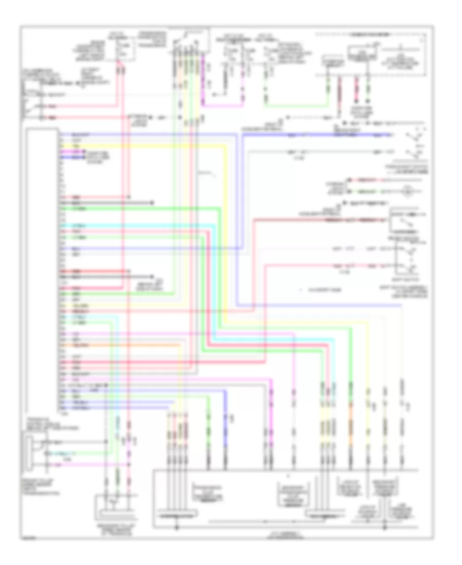
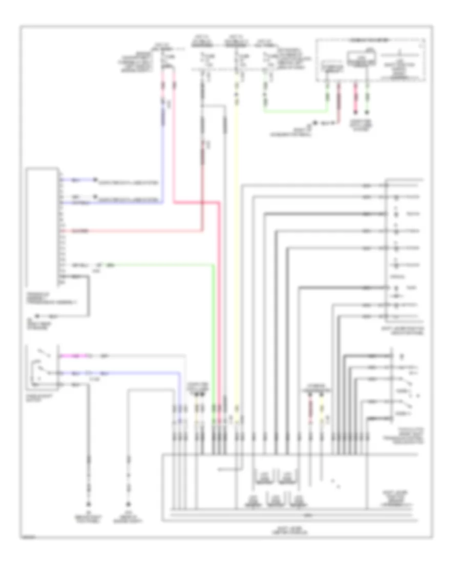
A/T Wiring Diagram, Except Evolution, TC-SST for Mitsubishi Lancer GT 2012
List of elements for A/T Wiring Diagram, Except Evolution, TC-SST for Mitsubishi Lancer GT 2012:
- A-54
- Acc relay 2 energized
- C-128
- C-315
- C-317
- C-49
- C-54
- Can transceiver circuit
- Combination meter
- Computer data lines system
- Cpu
- Engine compartment fuse/relay box (left side of engine compt)
- Etacs-ecu (on rear of junction block, behind left end of dash)
- Fuse 10a
- Fuse 15a
- Fuse 20a
- Fuse 7.5a
- G16 (rear of engine compt)
- G2 (right rear of engine)
- G4 (behind right kick panel)
- G5 (right of accelerator pedal)
- Hot at all times
- Hot w/
- Ig1 relay energized
- Ill
- Interface circuit
- Interior
- Lcd (shift position normal sport s-sport)
- Lights system
- Low side switch
- Manual
- Mode (+)
- Mode (-)
- Nca
- Paddle shift switch
- Pnk
- Shift lever (center console)
- Shift lever position indicator panel
- Shift lever position sensor (p,r,n,d,m,+,-)
- Transaxle assembly (transmission assembly)
- Twin clutch sport shift transaxle control module switch
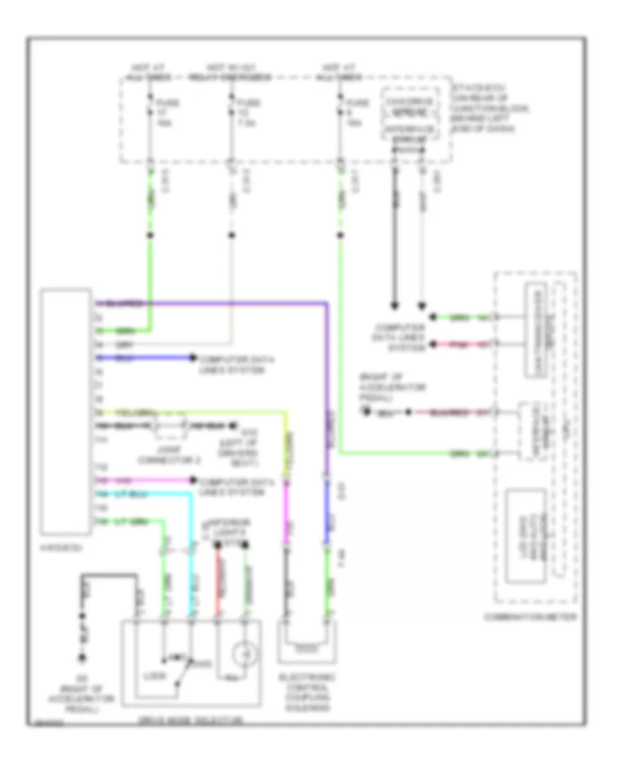
AWD Wiring Diagram for Mitsubishi Lancer GT 2012
List of elements for AWD Wiring Diagram for Mitsubishi Lancer GT 2012:
- (right of accelerator pedal) g5
- 2wd
- 4wd
- Awd-ecu
- C-301
- C-313
- C-315
- C-317
- C-35
- Can drive circuit
- Circuit can transceiver
- Circuit interface
- Combination meter
- Computer data lines system
- Cpu
- D-51
- Drive mode selector
- Electronic control coupling solenoid
- Etacs-ecu (on rear of junction block, behind left end of dash)
- F-44
- Fuse 10a
- Fuse 15a
- Fuse 7.5a
- G12 (left of drivers seat)
- G5 (right of accelerator pedal)
- Hot at all times
- Hot w/ ig1 relay energized
- Ill
- Interface circuit
- Interior lights system
- Joint connector 2
- Lcd (2wd 4wd auto 4wd lock)
- Lock
- Pnk